
Compact lens module

a lens module and compact technology, applied in the field of lenses modules, can solve the problems of disadvantageous complexity of driving tools and large size, and achieve the effect of compact size and short lens moving strok

Inactive Publication Date: 2005-09-08
SAMSUNG ELECTRO MECHANICS CO LTD
View PDF21 Cites 14 Cited by
  • Summary
  • Abstract
  • Description
  • Claims
  • Application Information

AI Technical Summary

Benefits of technology

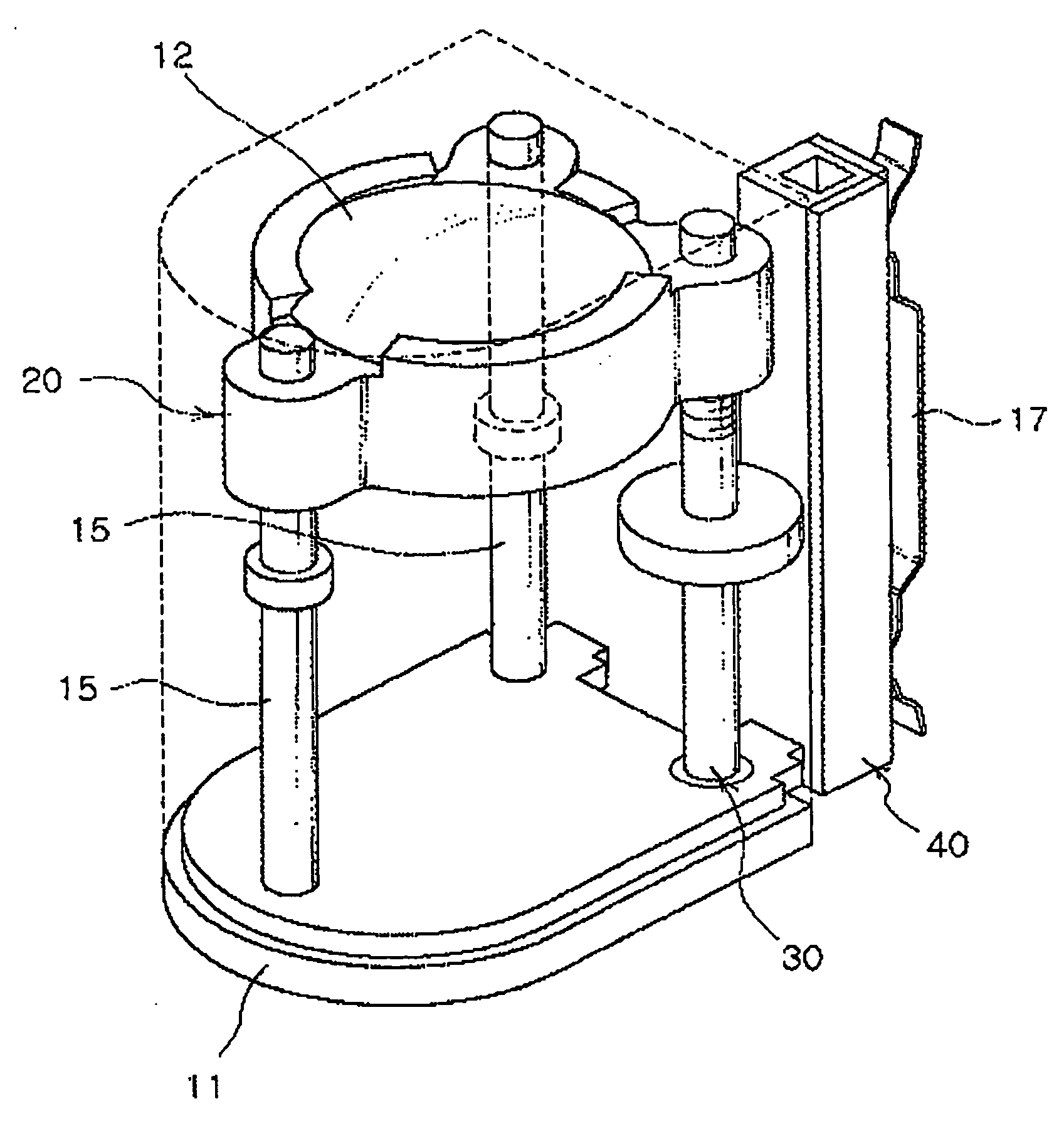
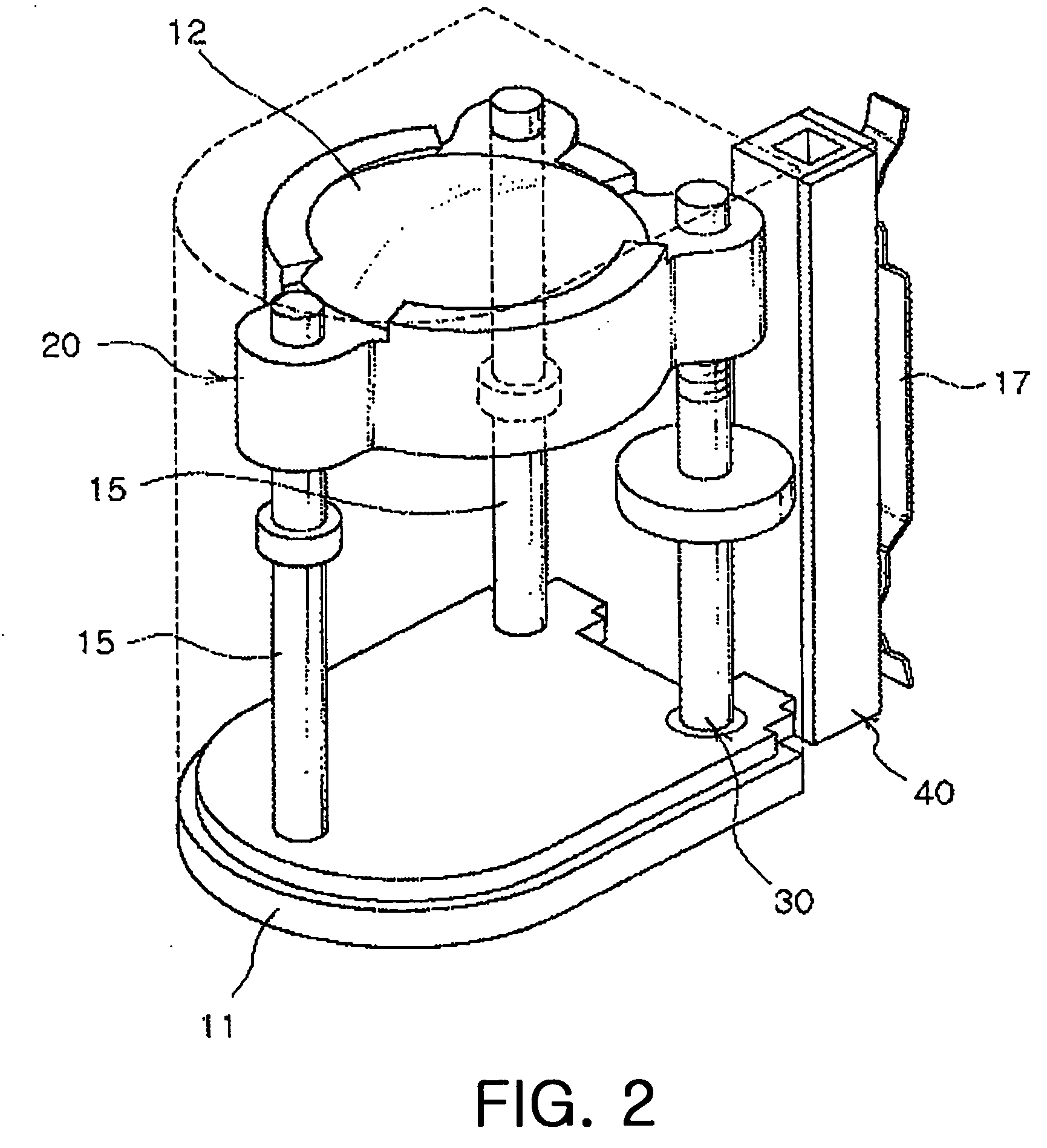
[0010] Accordingly, the present invention has been devised to solve the aforementioned problems, and an object of the present invention is to provide a lens module which may have a short lens moving stroke and a compact size by mounting a driving unit which operates with the use of supersonic frequency vibration.
[0011] Another object of the invention is to provide a lens module capable of operating accurately and having a compact size so that a small-size camera mounted to a small electronic machine may have a zoom function and an auto focus function.

Problems solved by technology

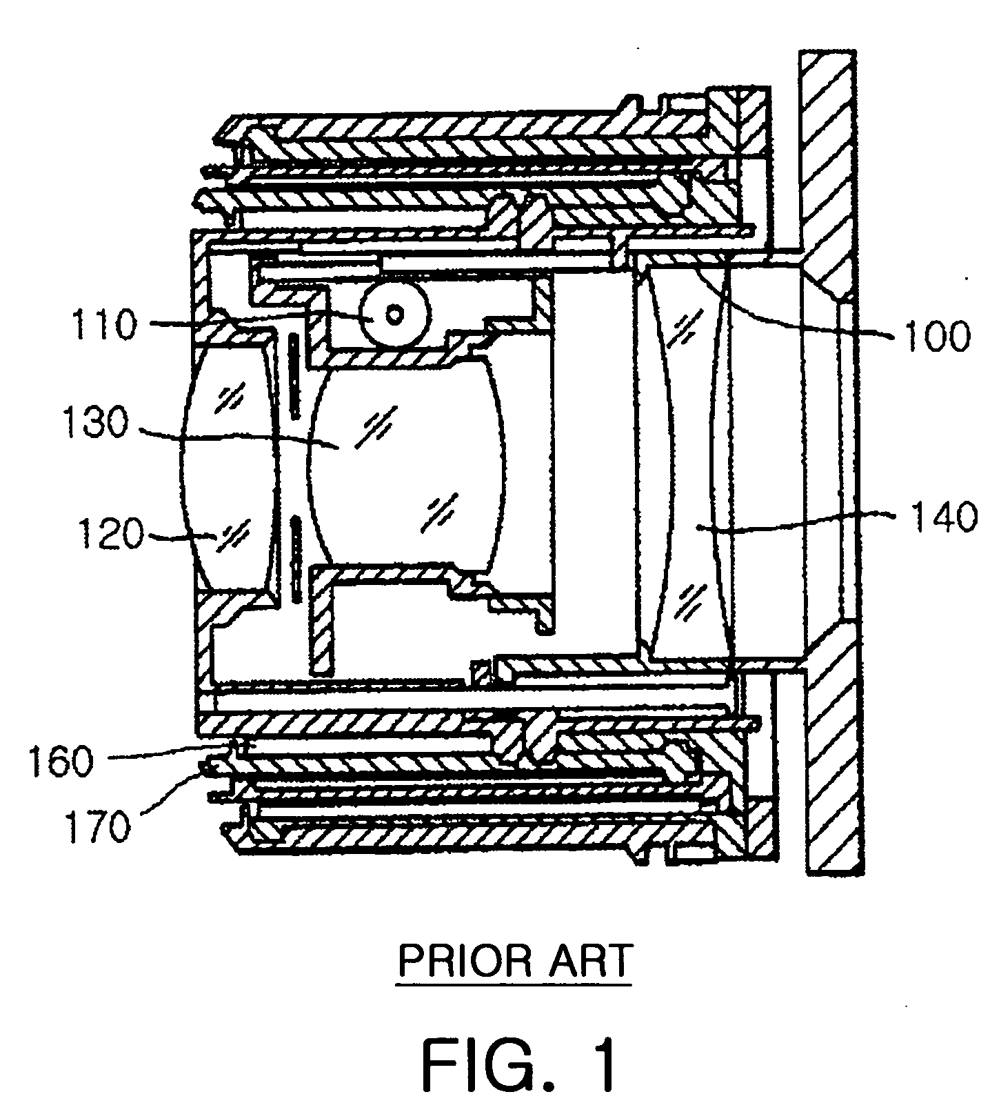
Thus, a focusing lens and a driving unit are additionally required for focusing at a specific magnification, and the driving tool becomes disadvantageously complicated and large-sized since a final reduction gear and a lens holding structure moving along the cam are further required.

Method used


Image

  • Compact lens module
  • Compact lens module
  • Compact lens module

Examples


Embodiment Construction

[0038] Hereinafter, preferred embodiments of the present invention will be described in detail with reference to the accompanying drawings.

[0039] A zoom function of an optical instrument such as a camera is realized by means of arrangement and movement stroke of each lens unit. The zoom function is used to photograph an object at a distance far from the optical instrument such as a camera as if it is positioned closer. Using the zoom camera, a larger image may be obtained for the same object. Meanwhile, the zoom function may be generally classified into an optical zoom function and a digital zoom function. The optical zoom function is defined to realize the zoom function according to the change of distance between lenses, which may advantageously compensate an image sensor of low resolution without deteriorating the image quality. On the while, the digital zoom function may advantageously give an image having high exposure at a specific position though the image quality is deterior...


PUM

PropertyMeasurementUnit
angleaaaaaaaaaa
driving forceaaaaaaaaaa
lengthaaaaaaaaaa

Abstract

Provided is a compact lens module which enables zoom and auto-focus functions even in a small lens module by providing a lens carrying structure using a supersonic driving unit. A lens unit is positioned in a case and has at least one lens. A carrying member is rotatably connected in the case and connected to the lens unit so that the lens unit may move forward and backward. In addition, a driving unit is mounted in the case for transferring a driving force to the carrying member so as to move the lens unit by repeatedly contacting and non-contacting with the carrying member.

Description

[0001] This application claims the benefit of Korean Patent Application No. 2004-14769 filed on Mar. 4, 2004, in the Korean Intellectual Property Office, the disclosure of which is incorporated herein by reference. BACKGROUND OF THE INVENITON [0002] 1. Field of the Invention [0003] The present invention relates to a lens module, and more particularly, to a compact lens module which enables zoom and auto-focus functions even in a small lens module by providing a lens carrying structure using a supersonic driving unit. [0004] 2. Description of the Related Art [0005] A camera technique is developed from a film camera using a film to a digital camera which converts an image into digital signals. Recently, such a digital camera is gradually miniaturized and begins to be applied to a personal mobile communication terminal. Quality of the digital camera mounted to the personal mobile communication terminal, for example a cellular phone, is based on the pixel number of the image sensor, whi...

Claims


Application Information

Patent Timeline
Patent Type & Authority Applications(United States)
IPC IPC(8): G02B7/04G02B7/02G02B7/10G11B7/00H02N2/00
CPCG03B3/10G02B7/102G02B13/003G02B13/009G03B2205/0061
Inventor JEONG, DAE HYUNKIM, OUI SERGCHOI, HYUNG MINJO, YONG JOORYU, JUNG HOSEOK, IL WOOCHO, JUNG KYUNKANG, BYUNG WOO
Owner SAMSUNG ELECTRO MECHANICS CO LTD
Learn More