Wireless communication system and apparatus

a wireless communication and wireless communication technology, applied in waveguides, instruments, optical elements, etc., can solve the problems of difficult to modify the position of the waveguide according to the environment, the installation efficiency in the office decreases, etc., to achieve the effect of reducing and standardizing the kinds of waveguides for antenna connection, easy placement, maintenance and operation, and economic and flexible modification

Inactive Publication Date: 2005-09-08
NEC CORP
View PDF1 Cites 6 Cited by
  • Summary
  • Abstract
  • Description
  • Claims
  • Application Information

AI Technical Summary

Benefits of technology

[0009] In the first conventional example, since any waveguide extends along the back side of the apparatus, working at the back side of the apparatus is indispensable when the apparatus is installed in the office or maintained and inspected. Accordingly, in the office, it is necessary to keep a large space at the back side of the apparatus to be installed. As a result, the installation efficiency in the office decreases.
[0011] An object of the present invention is to provide a wireless communication system, in which the position of a waveguide can be easily modified according to environment that receives the wireless communication apparatus, in which working for the installation and maintenance is possible with good efficiency, and in which the kind and number of the parts are small, and a wireless communication apparatus which is installed in the system.
[0014] The present invention has a first effect that it is possible to reduce and standardize the kinds of a waveguide for antenna connection. The reason is that the present invention makes it possible to modify a position at which a waveguide interface is disposed.
[0015] The present invention has a second effect that based on the first effect design, placement, maintenance and operation become easy. According to the present invention, for example, the position of the waveguide interface can be modified in consideration of an embodiment of an installation of the wireless communication apparatus or securement of working space around the apparatus, so individual design of each waveguide becomes unnecessary. According to the wireless communication system of the present invention, it also becomes possible to economically and flexibly modify a position for disposition of a waveguide, which is an antenna side interface of the wireless communication apparatus, according to environment for installation of the wireless communication apparatus, so the working space for the installation or the maintenance and inspection can be secured sufficiently.
[0016] The present invention has a third effect that based on the first effect the costs of system architecture is reduced. It is possible, for example, to standardize each waveguide or to reduce the number of kinds of the waveguides, so reduction of the costs and shortening of preparation time owing to an effect of mass production can be expected.

Problems solved by technology

As a result, the installation efficiency in the office decreases.
In the housing structure of the communication apparatus disclosed in JP-H05-31301-U, there is a problem that it is difficult to modify the position of the waveguide according to the environment to place the communication apparatus because the waveguides compose the frame of the housing, or that the kind and number of the parts such as the waveguide including the strengthening member, the coaxial cable, the conversion section and others increase.

Method used


Image

  • Wireless communication system and apparatus
  • Wireless communication system and apparatus
  • Wireless communication system and apparatus

Examples


examples

[0028] In order to describe the present invention in more detail, one example of the present invention is explained below, referring to the annexed drawings.

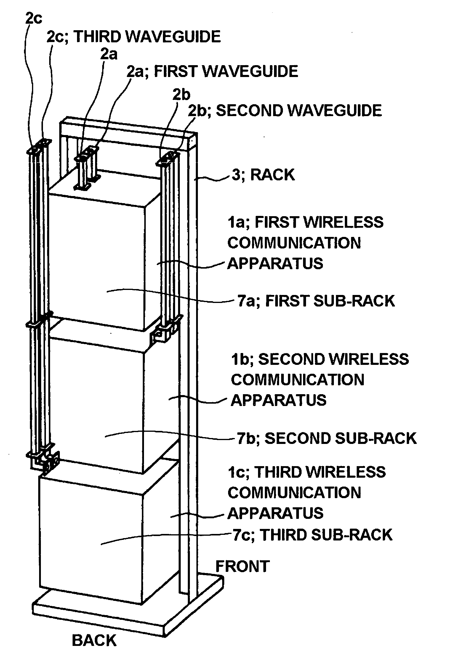
[0029]FIG. 1 is a figure showing constitution of a wireless communication system according to one example of the present invention.

[0030] Referring to FIG. 1, a wireless communication system according to one example of the present invention has first to third wireless communication apparatus 1a, 1b, 1c, namely, first to third hexahedral sub-racks 7a, 7b, 7c, installed in one rack 3. The first to third sub-racks 7a, 7b, 7c are stacked in turn from the top in the rack.

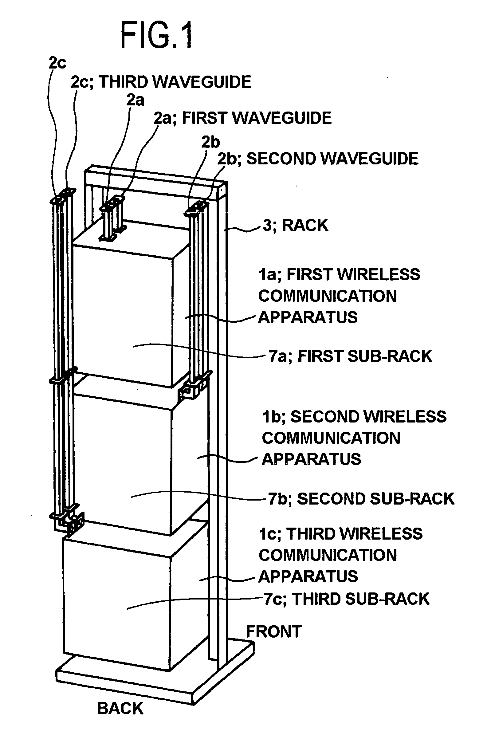
[0031] The first wireless communication apparatus 1a comprises a transmitting unit and receiving unit which are not shown, and first demultiplexing circuits (branches) 6a (referring to FIG. 2) which divide waves according to a frequency for transmission and reception, and these are installed in the sub-rack 7a together.

[0032] With regard to the constitution expla...


PUM


Abstract

A wireless communication system comprises a plurality of wireless communication apparatus, a plurality of sub-racks, and a rack. The wireless communication apparatus comprises a demultiplexing circuit, a cable to be connected to the demultiplexing circuit, a waveguide interface to be connected to the cable, and a waveguide to connect the waveguide interface and the antenna. A plurality of sub-racks for each housing the wireless communication apparatus to be connected to an antenna are installed in the rack. Among a plurality of the wireless communication apparatus which are different from one another, a pair of the waveguide interface and waveguide is disposed at a different position from other pair / pairs of waveguide interface and waveguide on a predetermined projectional plane. The waveguide assigned to each of the wireless communication apparatus extends along an outside of the sub-rack.

Description

FIELD OF THE INVENTION [0001] The present invention relates to a wireless communication system and wireless communication apparatus, and particularly, a wireless communication system and wireless communication apparatus of an intra-office placement type which are connected with an antenna via a waveguide. BACKGROUND OF THE INVENTION [0002] As an antenna side interface of a microwave band wireless communication apparatus, a waveguide is generally used. When the wireless communication apparatus is placed in an office or shelter, the antenna and the wireless communication apparatus are connected through the waveguide. [0003] In the wireless communication system architecture, it is required to reduce its costs. For achieving this goal, it is necessary to reduce the total costs, for example, the wireless communication apparatus itself, as well as the system design, the placement of the apparatus, the maintenance and the operation. [0004]FIG. 6 is a figure to explain constitution of a wir...

Claims


Application Information

Patent Timeline
Patent Type & Authority Applications(United States)
IPC IPC(8): H01P1/213G02B6/00H01P1/00H01P3/08H01P3/12H01Q1/00H04Q1/02H04Q1/14H05K7/18
CPCH04Q1/09G02B6/4452
Inventor SUGIYAMA, YUICHI
Owner NEC CORP
Why Eureka
Try Eureka