Electrical cardiac output forcer

a technology of cardiac output and electric field, applied in the field of forcing cardiac output, can solve the problems of large icd, unpractical for a truly prophylactic device, and inability to respond quickly enough for paramedics, and achieve the effect of maintaining life and consciousness

Inactive Publication Date: 2005-09-08
GALVANI
View PDF83 Cites 11 Cited by
  • Summary
  • Abstract
  • Description
  • Claims
  • Application Information

AI Technical Summary

Benefits of technology

[0009] In the implantable embodiment, a forcing field is generated by applying approximately 50 volts to the heart at a rate of approximately 100-180 beats per minute. These fields are applied after detection of an arrhythmia and maintained for up to several hours. This will generate a cardiac output which is a fraction of the normal maximum capacity. The heart has a 4 or 5 times reserve capacity so a fraction of normal pumping activity will maintain life and consciousness.

Problems solved by technology

Paramedics cannot usually respond rapidly enough with their external defibrillators to restore life.
While it works well at restoring normal function, the ICD is large in size and not practical for a truly prophylactic device.
In addition, external defibrillators are limited in their performance.
The defibrillation approach does not work satisfactorily.
External devices are too slow in arrival and implantable defibrillators are excessively large (and expensive) for prophylactic use.

Method used


Image

  • Electrical cardiac output forcer
  • Electrical cardiac output forcer
  • Electrical cardiac output forcer

Examples


Embodiment Construction

[0026] The present invention will now be described more fully hereinafter with reference to the accompanying drawings, in which preferred embodiments of the invention are shown. This invention may, however, be embodied in many different forms and should not be construed as limited to the embodiments set forth herein. Rather, Applicants provide these embodiments so that this disclosure will be thorough and complete, and will convey the scope of the invention to those skilled in the art.

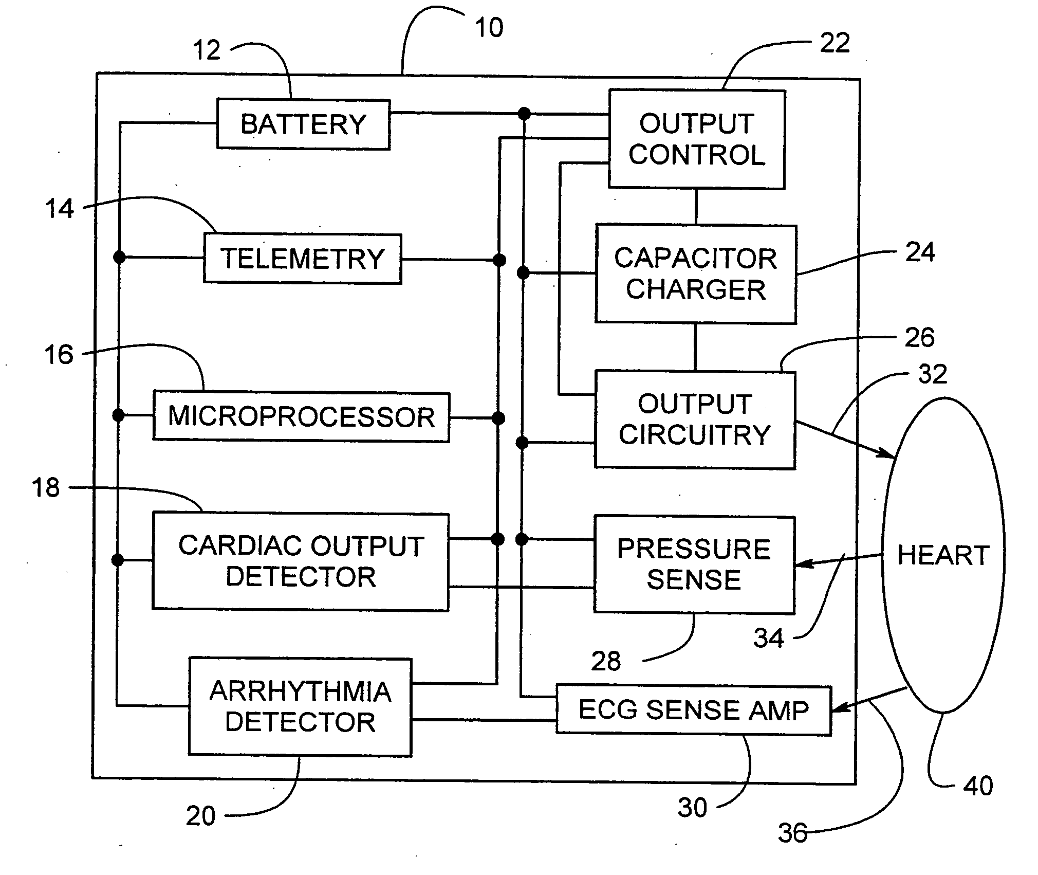
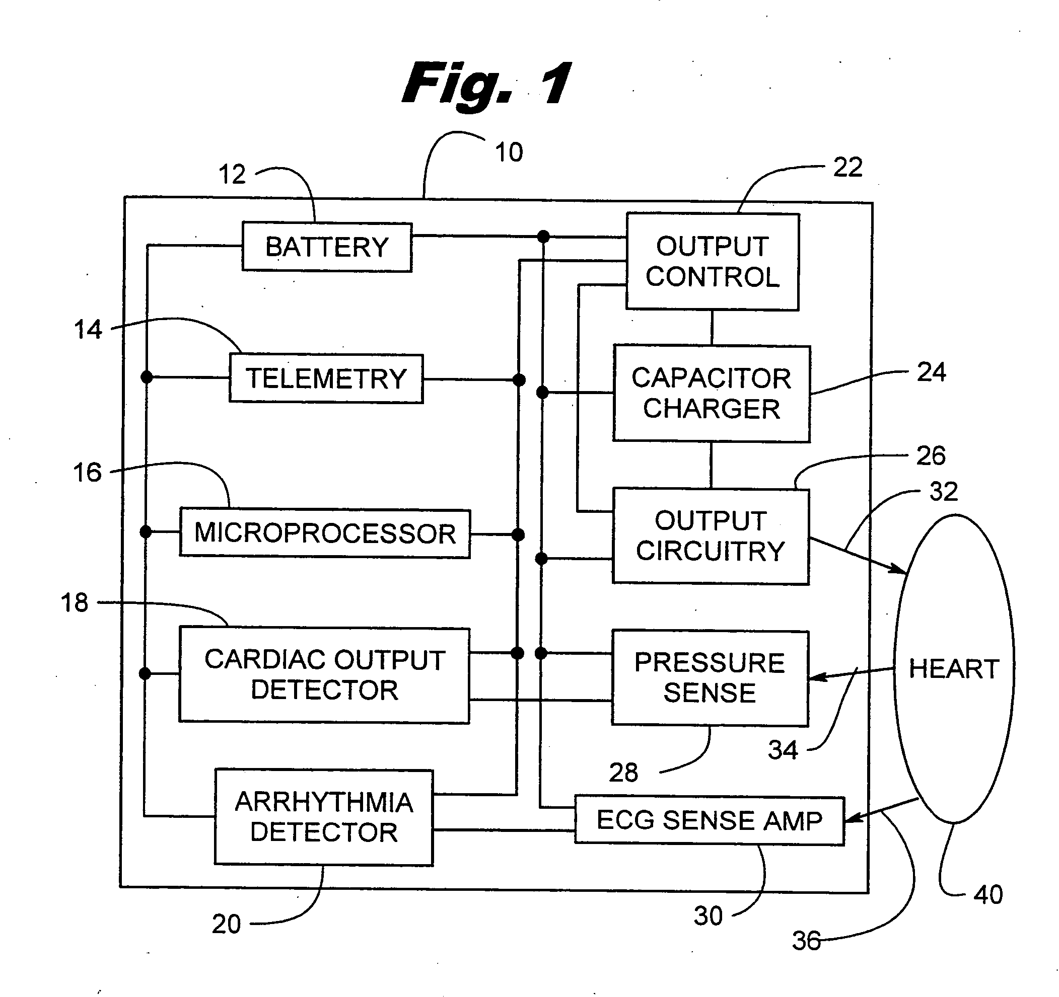
[0027]FIG. 1 is a block diagram illustrating a system 10 constructed in accordance with the principles of the present invention. The device circuitry is connected to the heart 40 via a series of leads; output lead 32, pressure sense lead 34, and ECG sense lead 36. The electronic circuit includes a conventional ECG amplifier 30 for amplifying cardiac signals. The amplified cardiac signals are analyzed by a conventional arrhythmia detector 20 which determines if an arrhythmia is present. The arrhythmia ...


PUM


Abstract

An electrical method and apparatus for stimulating cardiac cells causing contraction to force hemodynamic output during fibrillation, hemodynamically compromising tachycardia, or asystole. Forcing fields are applied to the heart to give cardiac output on an emergency basis until the arrhythmia ceases or other intervention takes place. The device is used as a stand alone external or internal device, or as a backup to an ICD, atrial defibrillator, or an anti-tachycardia pacemaker. The method and apparatus maintain some cardiac output and not necessarily defibrillation.

Description

RELATED APPLICATIONS [0001] This is a continuation application of U.S. patent application Ser. No. 09 / 693,551, filed Oct. 20, 2000, entitled, “ELECTRICAL CARDIAC OUTPUT FORCER;” which is a continuation of U.S. patent application Ser. No. 09 / 139,822, filed Aug. 25, 1998, entitled, “METHOD AND APPARATUS FOR ELECTRICALLY FORCING CARDIAC OUTPUT IN AN ARRHYTHMIA PATIENT,” now U.S. Pat. No. 6,167,306, issued Dec. 26, 2000; which is a continuation of U.S. patent application Ser. No. 08 / 754,712, filed Dec. 6, 1996, entitled, “METHOD AND APPARATUS FOR TEMPORARILY ELECTRICALLY FORCING CARDIAC OUTPUT IN A TACHYARRHYTHMIA PATIENT,” now U.S. Pat. No. 5,978,703, issued Nov. 2, 1999; which is a continuation of U.S. patent application Ser. No. 08 / 543,001, filed Oct. 13, 1995, entitled, “METHOD AND APPARATUS FOR TEMPORARILY ELECTRICALLY FORCING CARDIAC OUTPUTIN A TACHYARRHYTHMIA PATIENT,” now abandoned; which is a continuation of U.S. patent application Ser. No. 08 / 251,349, filed May 31, 1994, entit...

Claims


Application Information

Patent Timeline
Patent Type & Authority Applications(United States)
IPC IPC(8): A61N1/362A61N1/39
CPCA61N1/3625A61N1/395A61N1/3918
Inventor KROLL, KAIKROLL, MARK W.
Owner GALVANI
Why Eureka
Try Eureka