
Transformer having auxiliary winding coil for sensing magnetic flux balance and driving circuit using the same

a technology of transformers and winding coils, which is applied in the direction of transformers/inductance coils/windings/connections, fixed transformers, inductances, etc., can solve the problems of reducing the life of parts of lamps, unable to accurately detect if the energy provided to each lamp is balanced or not, and accelerated aging of parts of lamps. , to achieve the effect of maintaining the normal lifespan of lamps and preventing parts from aging

Inactive Publication Date: 2007-11-27
DELTA ELECTRONICS INC
View PDF8 Cites 7 Cited by
  • Summary
  • Abstract
  • Description
  • Claims
  • Application Information

AI Technical Summary

Benefits of technology

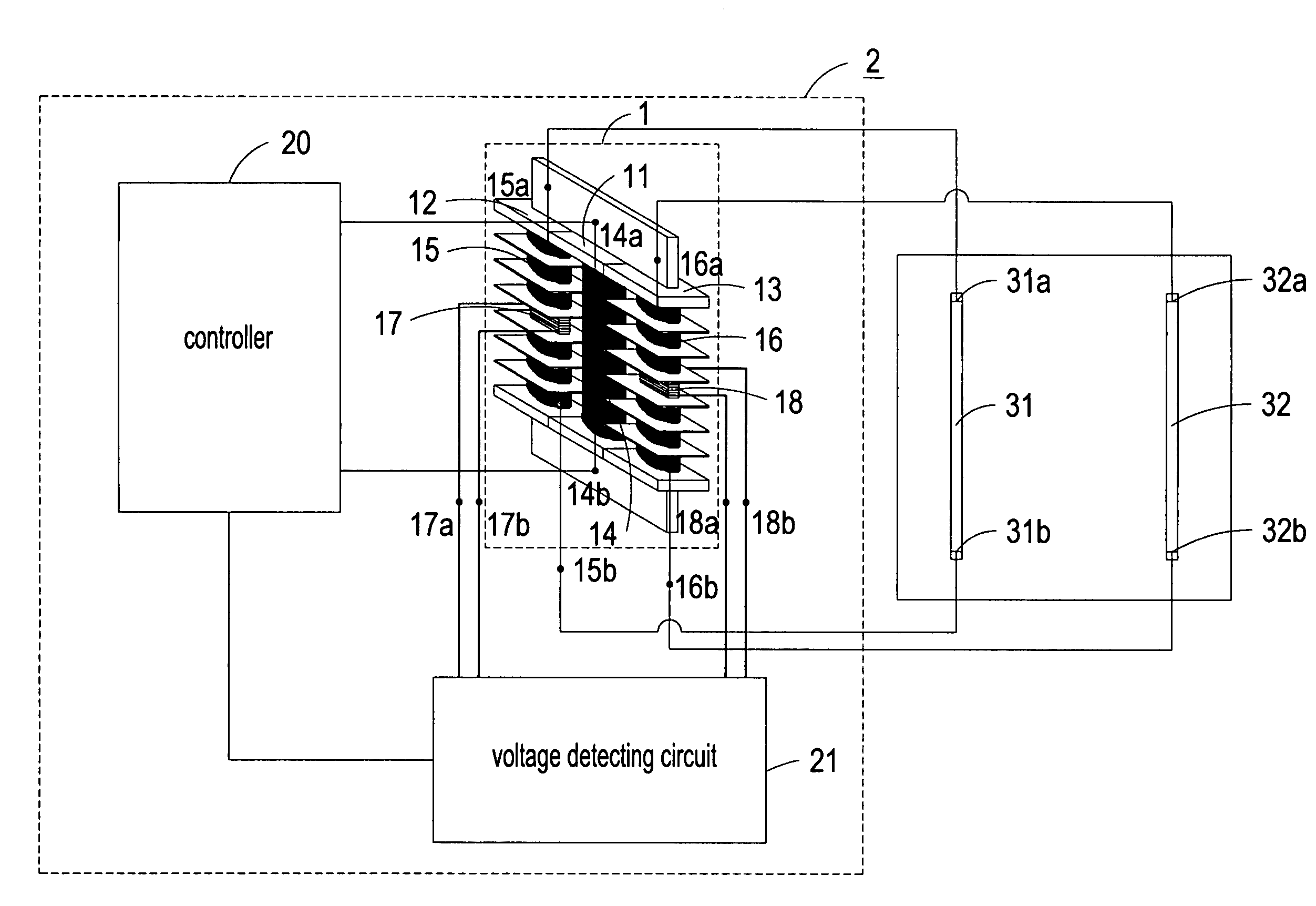
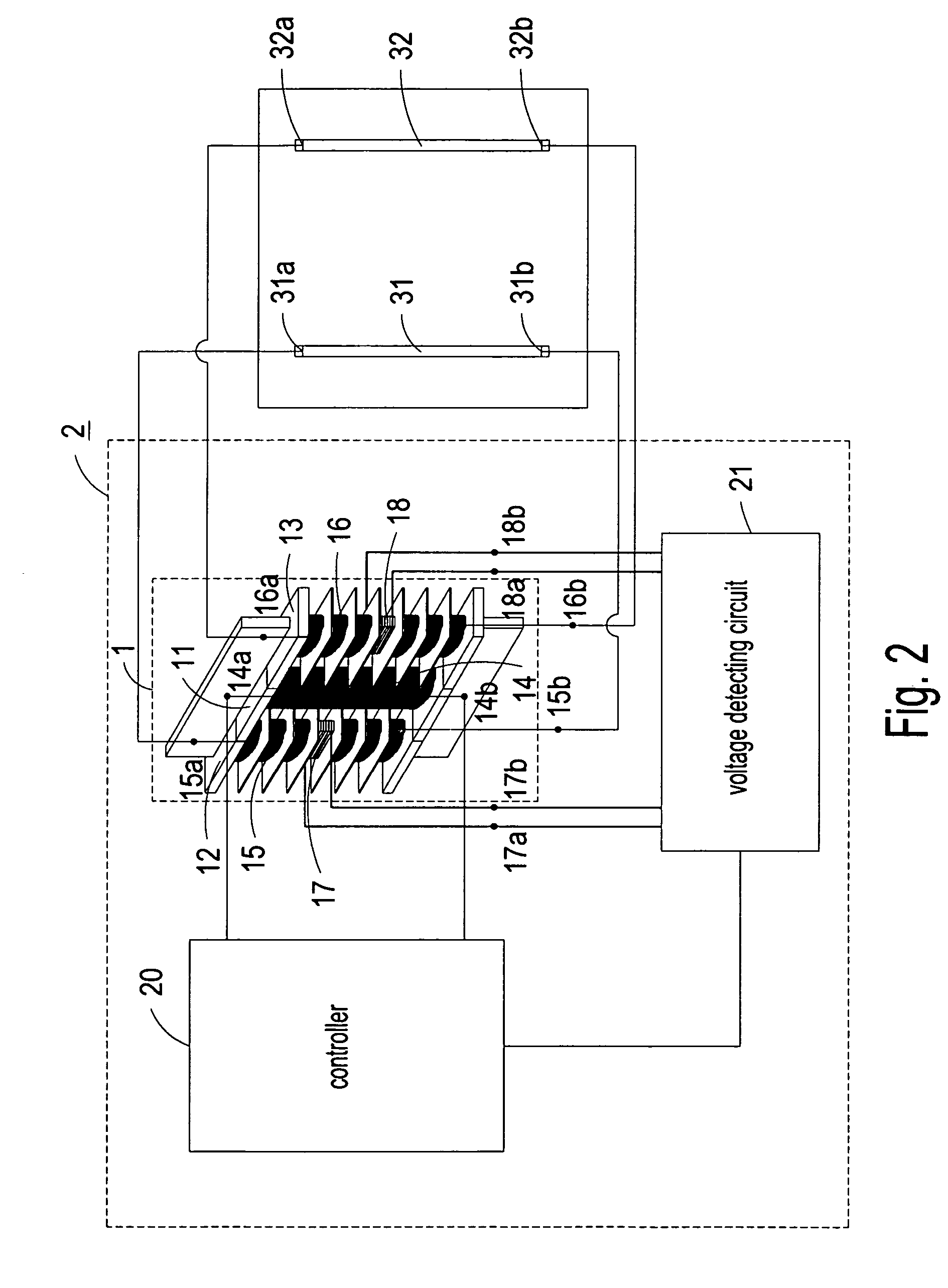
[0005]An object of the present invention is to provide a transformer having auxiliary winding coils for sensing magnetic flux balance and a driving circuit using the same. The present invention employs the transformer having the auxiliary winding coils coupled to the voltage detecting circuit for detecting if the energy provided to the plural lamps is substantially equal and executing proper controlling process, so as to ensure the even brightness of the LCD panel, prevent parts of the lamps from aging acceleratedly, and maintain the normal lifespan of the lamps.

Problems solved by technology

However, if the energy provided to each lamp is unequal, the LCD panel may have uneven brightness, and the lifespan of parts of the lamps might be shortened since their aging speed may be accelerated due to the unbalanced energy supply.
However, such method cannot accurately detect if the energy provided to each lamp is balanced or not.

Method used


Image

  • Transformer having auxiliary winding coil for sensing magnetic flux balance and driving circuit using the same
  • Transformer having auxiliary winding coil for sensing magnetic flux balance and driving circuit using the same
  • Transformer having auxiliary winding coil for sensing magnetic flux balance and driving circuit using the same

Examples


Embodiment Construction

[0014]The present invention will now be described more specifically with reference to the following embodiments. It is to be noted that the following descriptions of preferred embodiments of this invention are presented herein for purpose of illustration and description only; it is not intended to be exhaustive or to be limited to the precise form disclosed.

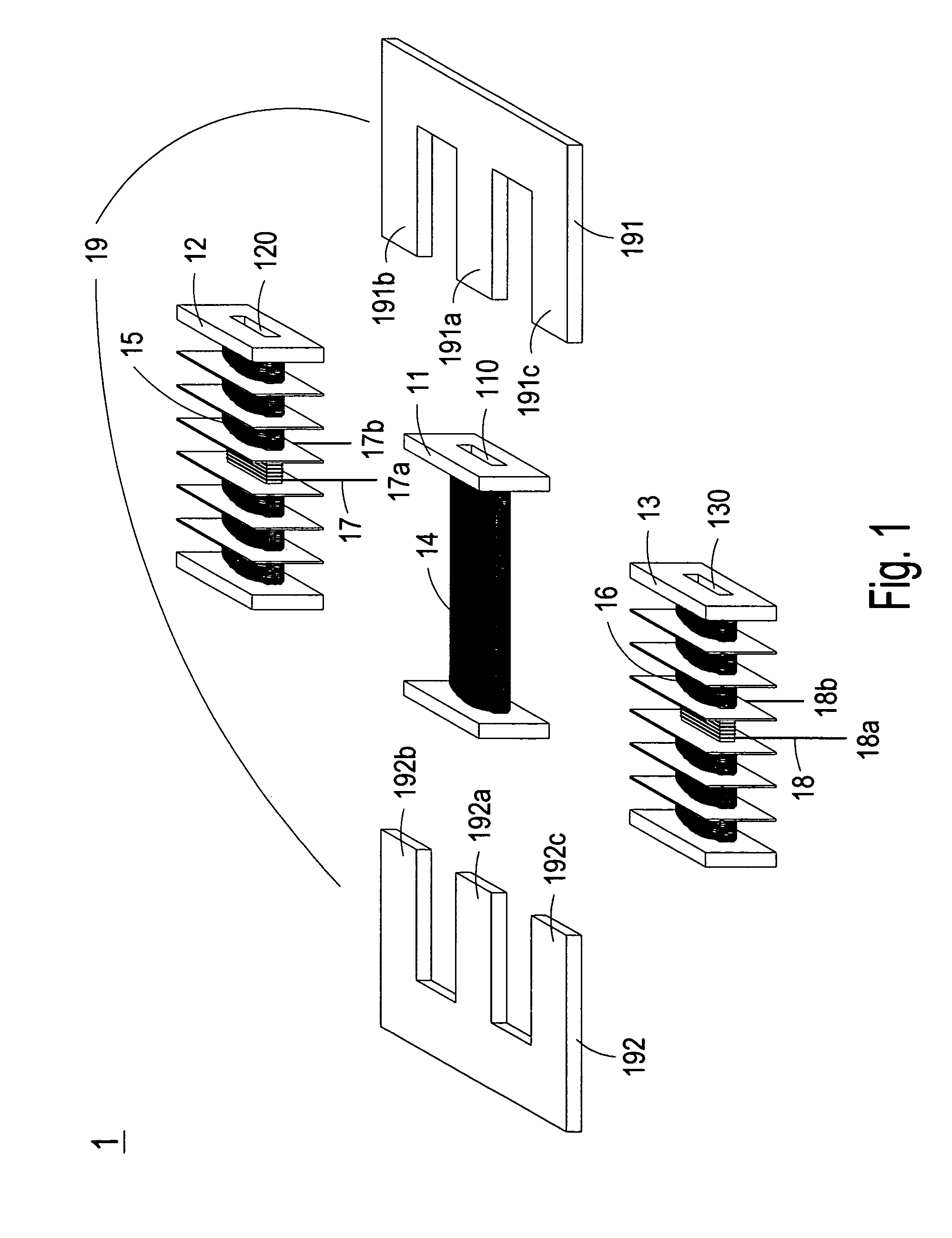
[0015]Please refer to FIG. 1, which is a schematic diagram showing the transformer having auxiliary winding coils for sensing magnetic flux balance according to the preferred embodiment of the present invention. As shown in FIG. 1, the transformer 1 comprises a first winding part 11, a second winding part 12, a third winding part 13, a primary winding coil 14, a first secondary winding coil 15, a second secondary winding coil 16, a first auxiliary winding coil 17 for sensing magnetic flux balance, a second auxiliary winding coil 18 for sensing magnetic flux balance, and a magnetic core assembly 19. The first winding part 11 has a...


PUM

PropertyMeasurementUnit
magnetic fluxaaaaaaaaaa
energyaaaaaaaaaa
magneticaaaaaaaaaa

Abstract

A transformer having auxiliary winding coils for sensing magnetic flux balance is disclosed. The transformer comprises a first winding part having a first channel, a second winding part having a second channel a third winding part having a third channel, a primary winding coil wound around the first winding part, a first secondary winding coil wound around the second winding part, a second secondary winding coil wound around the third winding part, a first auxiliary winding coil for sensing magnetic flux balance wound around the second winding part, a second auxiliary winding coil for sensing magnetic flux balance wound around the third winding part, and a magnetic core assembly having a first extension part disposed in the first channel, a second extension part disposed in the second channel, and a third extension part disposed in the third channel. The first and the second secondary winding coils couple to a plurality of lamps for providing energy to the plurality of lamps, and the first and the second auxiliary winding coils couple to a voltage detecting circuit for detecting if the energy provided to the plurality of lamps is substantially equal.

Description

FIELD OF THE INVENTION[0001]The present invention relates to a transformer and a driving circuit using the transformer, and more particularly to a transformer having auxiliary winding coils for sensing magnetic flux balance and a driving circuit using the same.BACKGROUND OF THE INVENTION[0002]With the progress of technology, the panel display has been extensively used in the daily life. Take the liquid crystal display (LCD) panel as an example. The LCD panel mainly comprises an LCD module, a backlight module and a power module. The backlight module uses plural cold cathode fluorescent lamps (CCFL) or external electrode fluorescent lamps (EEFL) as light source, and these lamps are driven by a driving circuit called inverter.[0003]Since the size of the LCD panel becomes larger and larger, the amount and size of the lamps are also increased. However, if the energy provided to each lamp is unequal, the LCD panel may have uneven brightness, and the lifespan of parts of the lamps might be...

Claims


Application Information

Patent Timeline
Patent Type & Authority Patents(United States)
IPC IPC(8): H01F27/28
CPCH01F27/38H05B41/2822H01F30/04H01F38/10H01F30/06
Inventor CHANG, SHIH-HSIEN
Owner DELTA ELECTRONICS INC
Learn More