Intervertebral disc prosthesis

Active Publication Date: 2005-09-08
LDR MEDICAL
View PDF99 Cites 203 Cited by
  • Summary
  • Abstract
  • Description
  • Claims
  • Application Information

AI Technical Summary

Problems solved by technology

However, because of the forces from applied constraints, materials utilized and the form of the different pieces constituting the prosthesis, the sliding of the core is often d

Method used


Image

  • Intervertebral disc prosthesis
  • Intervertebral disc prosthesis
  • Intervertebral disc prosthesis

Examples


Embodiment Construction

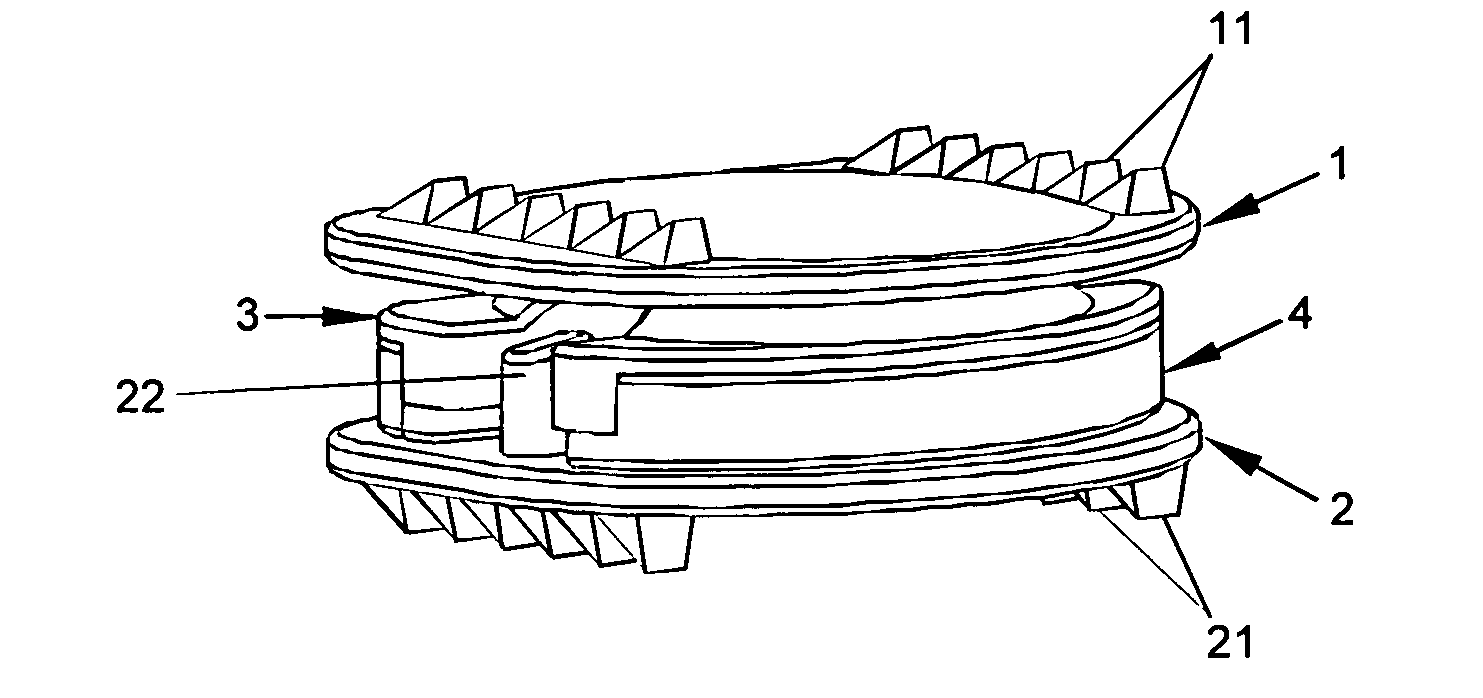
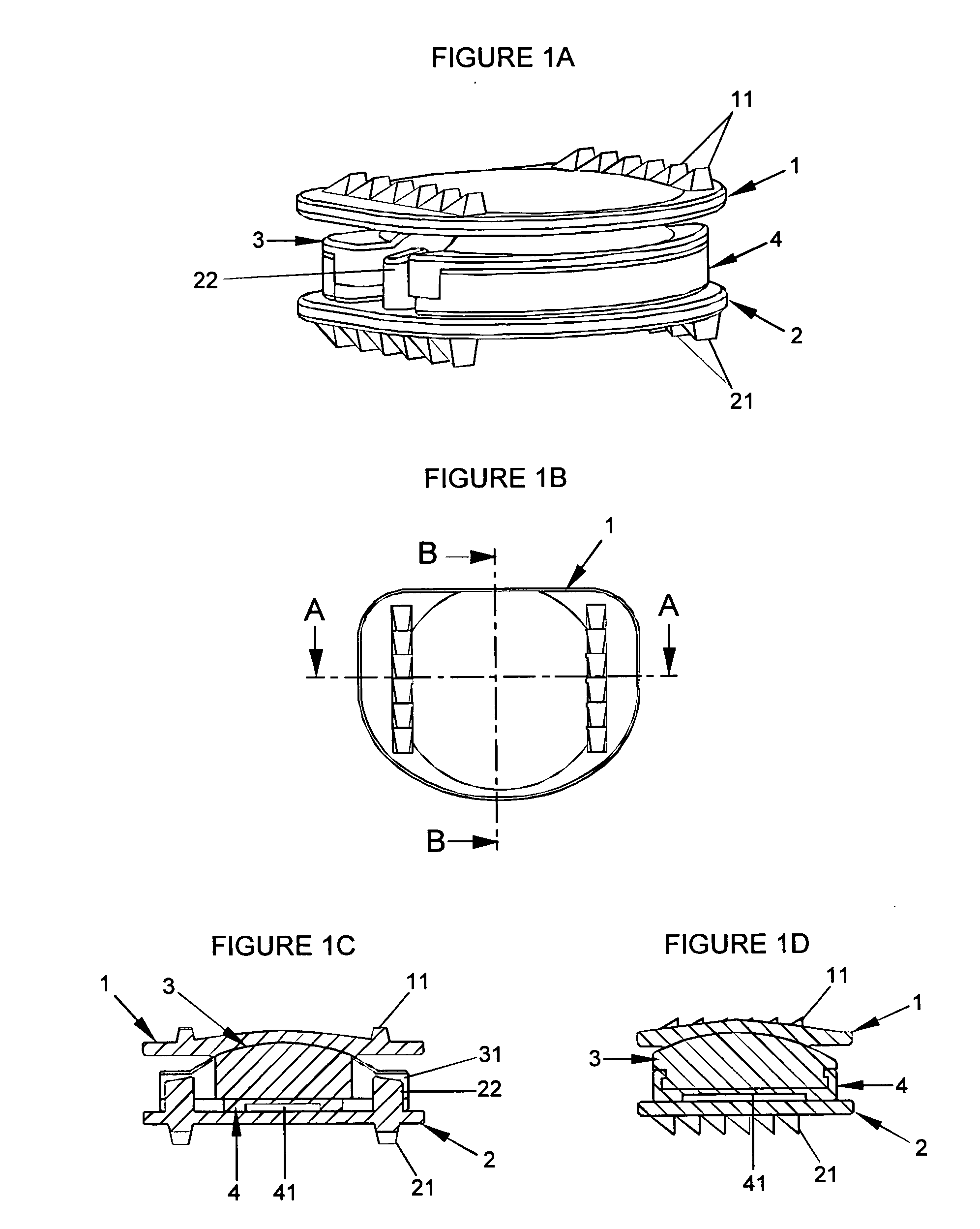
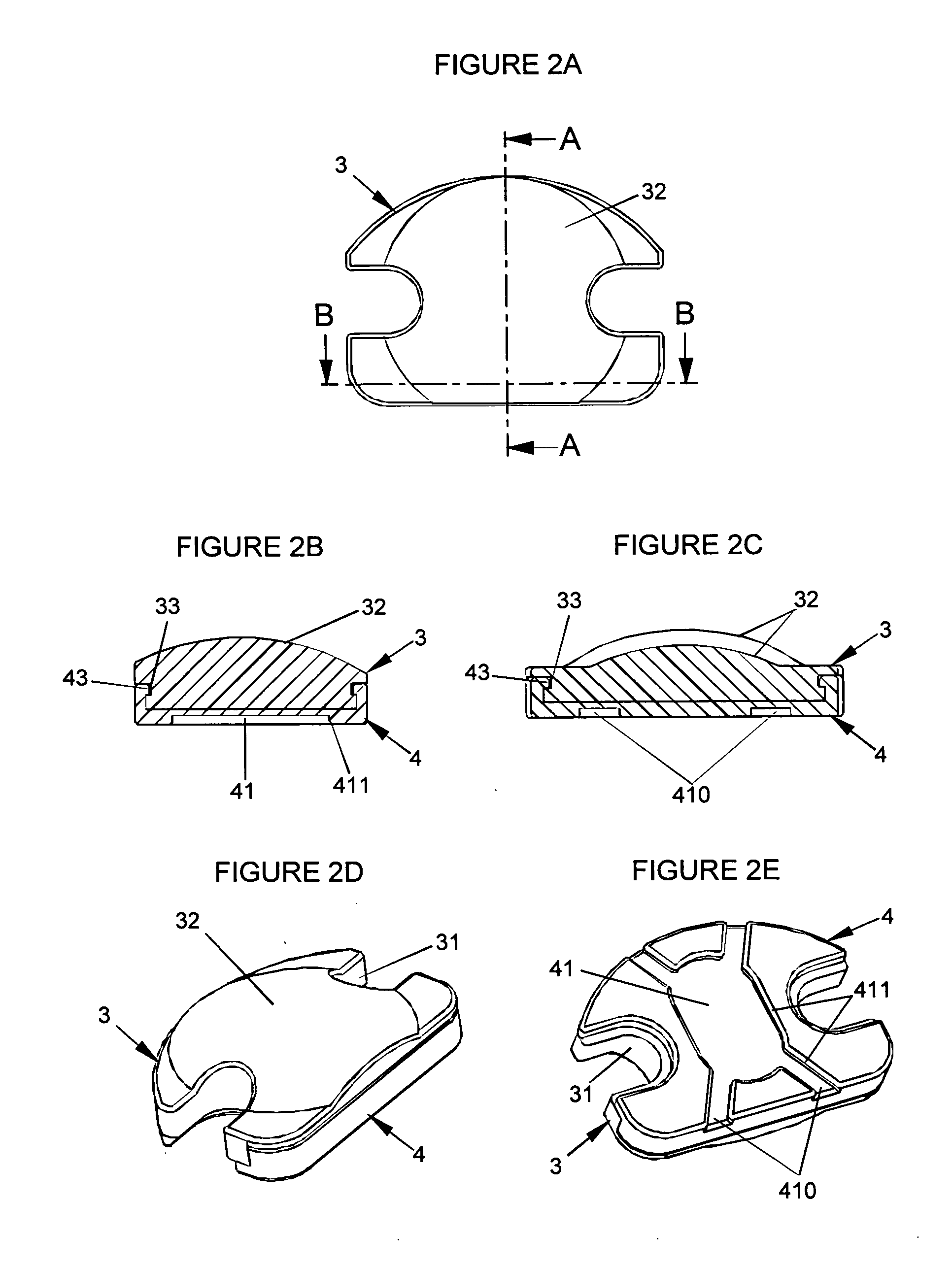
[0053] The intervertebral disc prosthesis according to an embodiment of the present invention is comprised of a first plate (1) articulated relative to a second plate (2) by means of a core (3), as evident in particular in FIGS. 1a, 1c and 1d. In the following description, the first plate (1) is called the upper plate and the second plate (2) is called the lower plate, according to the orientation given to the prosthesis shown in the drawings. Those of skill will recognize after appreciating this disclosure that the prosthesis could be inversely oriented between the vertebrae, so that the first plate (1) would be the lower plate and the second plate (2) would be the upper plate. An advantage of the prosthesis according to the present invention is that it comprises simple pieces which can be dimensioned so that the prosthesis is placed on the cervical spine.

[0054] The core (3) is of less thickness (for example 3 mm in a preferred embodiment) for a cervical prosthesis or thicker (for...


PUM


Abstract

The present invention relates to an intervertebral disc prostheses that comprise at least three pieces including an upper plate (1), a lower plate (2) and a mobile core (3) at least relative to the lower plate (2), the upper surface of the core (3) being in contact with at least a part of the lower surface of the upper plate (1), limit stops (22, 31) allowing friction to be limited, while limiting or preventing the movements of the core (3) relative to the lower plate (2), in translation and in rotation, respectively, along an axis substantially parallel to the lower plate (2) and about an axis substantially perpendicular to the lower plate (2) and the lower surface of the core (3) has at least one hole (41) facilitating sliding of the core (3) relative to the upper surface of the lower plate (2) with which it is in contact.

Description

TECHNICAL FIELD [0001] The present invention relates to intervertebral disc prostheses. BACKGROUND OF THE INVENTION [0002] Various types of prostheses are known in the prior art. Numerous prostheses are constituted by a lower plate and an upper plate enclosing a central core. A part of these prostheses enables the upper plate to slide relative to the central core and optionally permits the central core to slide relative to the lower plate. This sliding of the central core relative to the lower plate allows spontaneous positioning of the core in the ideal position to absorb constraints imposed on the prosthesis during movements made by the patient carrying the prosthesis. However, because of the forces from applied constraints, materials utilized and the form of the different pieces constituting the prosthesis, the sliding of the core is often difficult, which causes rapid wear and heightens the risk of ejection of at least a part of the prosthesis to the outside of the spine, and th...

Claims


Application Information

Patent Timeline
IPC IPC(8): A61B17/34A61B17/86A61F2/00A61F2/30A61F2/44A61F2/46
CPCA61B17/3468A61F2220/0033A61F2/0095A61F2/30767A61F2/4425A61F2/4611A61F2002/30331A61F2002/30365A61F2002/30367A61F2002/30369A61F2002/30387A61F2002/30476A61F2002/30571A61F2002/30616A61F2002/30649A61F2002/30662A61F2002/30673A61F2002/30685A61F2002/30795A61F2002/30841A61F2002/30904A61F2002/30937A61F2002/443A61F2002/4622A61F2002/4627A61F2220/0025A61B17/3472
Inventor HOVORKA, ISTVANBERNARD, PIERRE
Owner LDR MEDICAL
Why Eureka
Try Eureka