Ablative afterburner

Inactive Publication Date: 2005-09-15
GENERAL ELECTRIC CO
View PDF17 Cites 21 Cited by
  • Summary
  • Abstract
  • Description
  • Claims
  • Application Information

AI Technical Summary

Problems solved by technology

Gas turbine engines are highly sophisticated and complex and include many individual parts which must be separately manufactured and assembled in the final engine.
The number of parts required in a particular engine directly affects the complexity thereof and the associated manufacturing cost.
And, cost is particularly significant in manufacturing gas turbine engines for expendable applications, or for a limited number of uses.
However, for applications requiring supersonic operation at greater than the speed of sound, the engines require additional propulsion thrust.
The exhaust nozzle is particularly complex since it mu

Method used


Image

  • Ablative afterburner
  • Ablative afterburner
  • Ablative afterburner

Examples


Embodiment Construction

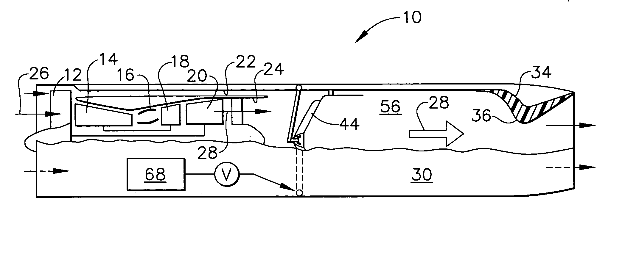
[0025] Illustrated schematically in FIG. 1 is an augmented turbofan gas turbine engine 10 configured for powering an aircraft in flight. The engine is specifically configured for powering an expendable single-use aircraft, such as a cruise missile, or a limited-use aircraft such as a remotely piloted drone aircraft, for example.

[0026] The engine is axisymmetrical about a longitudinal or axial centerline axis and includes in serial flow communication a fan 12, multistage compressor 14, combustor 16, high pressure turbine (HPT) 18, and low pressure turbine (LPT) 20. Each of the turbines includes corresponding turbine nozzles and rows of turbine rotor blades.

[0027] The rotor blades of the HPT 18 are supported from a rotor disk joined by one shaft to the corresponding rotors of the multistage compressor 14. The turbine blades of the LPT 20 are supported by another rotor disk which in turn is joined to the fan 12 by another shaft extending axially therebetween.

[0028] Surrounding the c...


PUM


Abstract

An afterburner includes an exhaust duct with a fixed area outer nozzle at an aft end thereof, and an ablative inner nozzle therein. The smaller inner nozzle is consumed during reheat operation to expose the larger outer nozzle for increased propulsion thrust.

Description

BACKGROUND OF THE INVENTION [0001] The present invention relates generally to gas turbine engines, and, more specifically, to augmented engines. [0002] Gas turbine engines are available in a variety of configurations, sizes, and output thrust. The typical turbofan engine includes in serial flow communication a fan, multistage compressor, combustor, high pressure turbine (HPT), and low pressure turbine (LPT). The HPT is joined to the compressor by one shaft, and the LPT is joined to the fan by another shaft. [0003] In operation, air enters the engine and flows past the fan and into the compressor wherein it is pressurized and discharged to the combustor. Fuel is added to the compressed air in the combustor for generating hot combustion gases which are discharged through the turbine stages. [0004] The HPT includes rotor blades which extract energy from the combustion gases for rotating the supporting disk joined to the shaft which powers the compressor. The combustion gases then flow ...

Claims


Application Information

Patent Timeline
IPC IPC(8): F02K1/06F02K1/82F02K3/10F02K9/10F02K9/97F23M5/00F23R3/20
CPCF02K1/06F02K1/822F02K3/10F23R3/20F02K9/974F23M5/00F02K9/10
Inventor KOSHOFFER, JOHN MICHAELLEWIS, RANDY LEE
Owner GENERAL ELECTRIC CO
Why Eureka
Try Eureka