Dual Chamber System for Gasifying Biomass Waste

a gasification system and biomass waste technology, applied in the direction of combustion process, lighting and heating apparatus, combustion types, etc., can solve the problems of increasing the volume of remaining biomass, increasing the production of fly-ash into the fumes, and increasing the cost of gasification

Inactive Publication Date: 2008-12-18
ZEBREX ENVIRONMENTAL SYST
View PDF14 Cites 17 Cited by
  • Summary
  • Abstract
  • Description
  • Claims
  • Application Information

AI Technical Summary

Benefits of technology

[0055]There are first and second secondary burner members in the incinerator and gasifier which are such as to produce an initial flame within a first vertically disposed portion of each of the first and second afterburner chambers, respectively, and wherein each of the first and second secondary burner members has a respective fuel inlet and an air inlet to permit the supply of fuel and oxygen to the respective secondary burner members There are also first and second control means to control the supply of fuel and oxygen to the respective first and second secondary burner members;

Problems solved by technology

If the external heat energy introduced into the biomass material is at a very high temperature or is applied very abruptly, especially in a concentrated area, then two things tend to happen: Firstly, any reactions that occur tend to be rather violent, thus causing the production of fly-ash into the fumes of the volatilizing biomass; secondly, the sudden and concentrated reactions produce a large amount of heat energy, which in turn can cause the abrupt volatilization of the surrounding material, which volatilization can be somewhat violent.
Further, if a substantial amount of material is volatilized, in the manner discussed immediately above, over a relatively short period of time, then the ambient temperature of the primary chamber will tend to rise substantially, thus causing the remaining biomass to be volatilized more quickly, but not at a controlled rate.
In other words, the reaction is, at least to some degree, out of control.
It is found, however, that the fumes that are driven off contain a great quantity of materials, such as fly-ash, having hydrogen-carbon bonds, and other unincinerated materials.
However, relatively large pieces of material, such as fly-ash, may contain several million or billion molecules; and, accordingly, such pieces of material as are borne by the fumes may not get fully incinerated in the time that they take to pass through the afterburner chamber 7.
The flame tends to cause the biomass waste to inflame and also tends to physically agitate the biomass 4.
As a result, an undesirably high amount of fly-ash is included within the fumes from the burning biomass 4.
Further, this type of conventional prior art incinerator 1 does not provide sufficient heat intensity on an overall basis to properly incinerate all of the waste material.
There is often not enough heat intensity to cause complete gasification even of the materials that do burn, and certainly not enough heat intensity to cause complete gasification of the waste material at the centre of the biomass.
It has been found that typically there is also undesirable material such as dioxins, furans and organo-chlorides, and other organic matter.
Such incineration by way of direct radiant heat tends to cause burning of the biomass 9 so as to cause premature ignition which leads to incomplete combustion in the early stages of the process.
It has been found that the use of such multiple control systems tends to produce an overall system wherein the temperature in the primary chamber may vary and, therefore, cannot be considered stable.
Such lack of stability is caused by the plurality of control systems essentially working against each other.
It has been found that such prior art incinerators and cremators as discussed above, due to the inherent nature of the incineration process that occurs, produce an unacceptable end product.
The fumes that are produced have relatively high levels of hydro-carbons, dioxins, furans, among other materials and substances, and also may contain fly-ash, while the resulting ash remaining in the incinerator may have unwanted organic matter such as bacteria, viruses, and other microorganisms.
It can therefore be seen that incineration of biomass waste and related volatile solids is generally unacceptable as it does not render potentially infectious waste totally safe.

Method used


Image

  • Dual Chamber System for Gasifying Biomass Waste
  • Dual Chamber System for Gasifying Biomass Waste
  • Dual Chamber System for Gasifying Biomass Waste

Examples


Embodiment Construction

[0065]The novel features which are believed to be characteristic of the present invention, as to its structure, organization, use and method of operation, together with further objectives and advantages thereof, will be better understood from the following discussion.

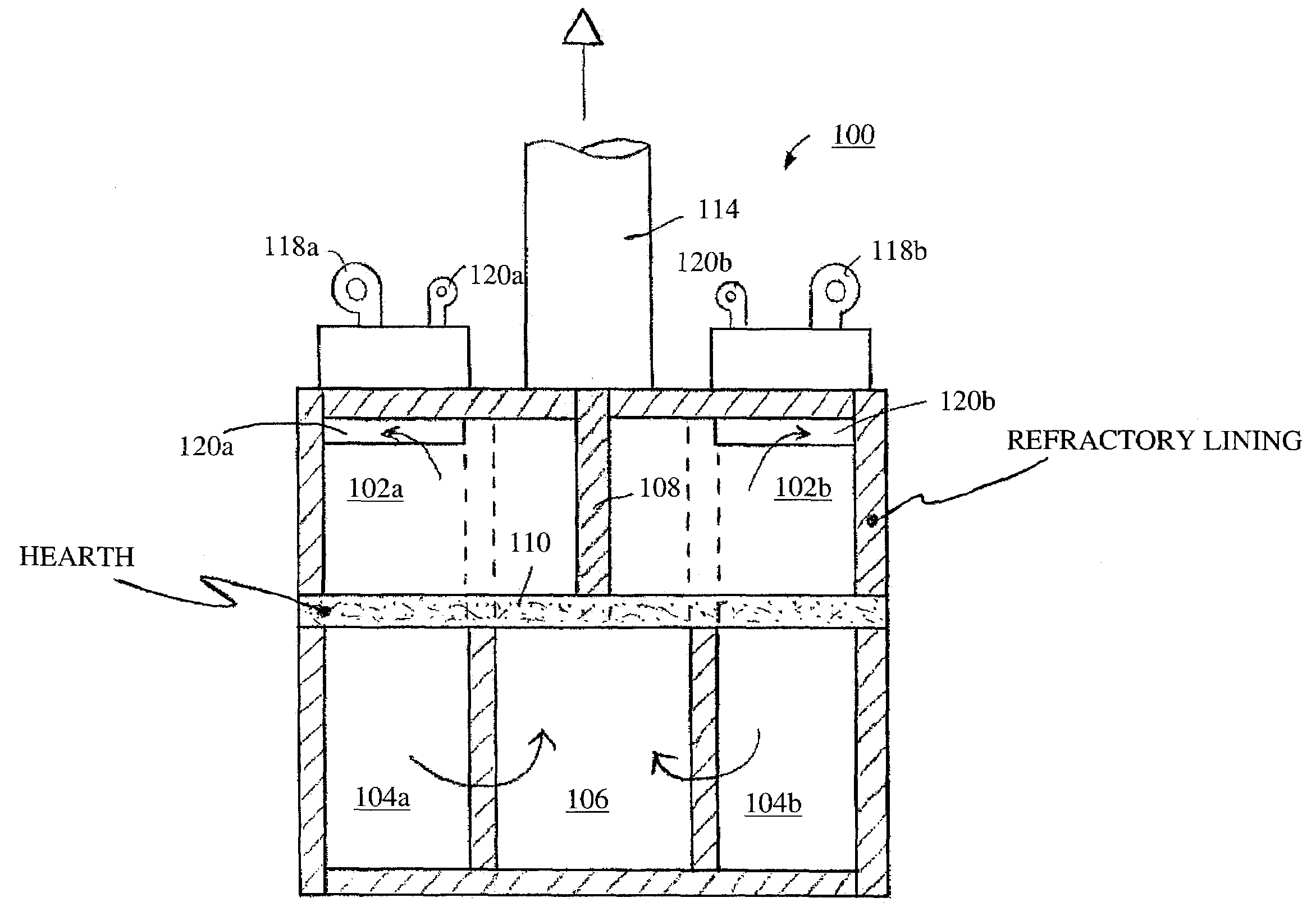
[0066]Turning first to FIGS. 5 and 6, simplified views of a biomass gasifier and incinerator in keeping with the present invention are shown. The biomass gasifier and incinerator is identified generally with the numeral 100, and comprises two primary chambers 102a and 102b, two afterburner chamber 103a and 103b, two secondary chambers 104a and 104b, and an exhaust duct 106. As will be described hereafter, a biomass load will be placed into primary chamber 102a, and after a prescribed period of time another biomass load will be placed into primary chamber 102b. Typically, that prescribed period of time is one half the time that it will take the load in the first primary chamber to become totally incinerated and gasified....


PUM


Abstract

A device for gasifying biomass waste has two each of primary chambers, fume transfer vents, mixing chambers which accept fumes from the primary chamber, afterburner chambers in fluid communication with the mixing chambers, and an exhaust duct. Each secondary burner produces an initial heating flame within a vertical portion of the respective afterburner chamber, and secondary chambers are in fluid communication with the afterburner chambers. Heated gases from the afterburner chambers cause heating of the secondary chambers. A portion of each primary chamber has a heat conductive floor superimposed over the respective secondary chamber, and the partition between the primary chambers is heat conductive, so that conductive and convective heating of the primary chambers occurs.

Description

STATEMENT OF GOVERNMENT INTEREST[0001]This project is being funded by the U.S. government under TSWG Contract No. W91CRB-06-C-0007 and the U.S. government has certain rights in this invention.FIELD OF THE INVENTION[0002]This invention relates to incinerators and gasifiers for processing biomass waste, and particularly for processing biomass waste in alternating batches through one or the other of two adjacent primary incineration chambers, in such a manner that the biomass waste may be said to be disposed of in a “continuing batch loading system”. As will be discussed hereafter, incinerators and gasifiers in keeping with the present invention share an exhaust flow system, but otherwise they comprise two separately operated primary and secondary incineration and gasification systems whose shared exhaust gases are environmentally benign.BACKGROUND OF THE INVENTION[0003]While discussion of the present invention, hereafter, will relate to its potential mobility, the main intent of the p...

Claims


Application Information

Patent Timeline
Patent Type & Authority Applications(United States)
IPC IPC(8): F23B10/00
CPCF23G1/00F23G5/0273F23G5/165F23G7/10F23G2201/40F23G2202/101F23G2202/102F23G2202/103
Inventor BROOKES, DAVID
Owner ZEBREX ENVIRONMENTAL SYST
Why Eureka
Try Eureka