Method and apparatus for providing an afterburner fuel-feed arrangement

a fuel-feed arrangement and afterburner technology, which is applied in the direction of machines/engines, continuous combustion chambers, lighting and heating apparatus, etc., can solve the problems of affecting the throughput of the engine, affecting the efficiency of the engine, so as to reduce the stress, reduce the thermal stress of the shroud, and reduce the transfer of heat between the pipes and the shroud.

Inactive Publication Date: 2006-02-16
VOLVO AERO CORP
View PDF20 Cites 17 Cited by
  • Summary
  • Abstract
  • Description
  • Claims
  • Application Information

AI Technical Summary

Benefits of technology

[0010] In this embodiment, the shroud has an interior lateral sidewall that includes a pipe-receiving portion. The pipe-receiving portion is configured to abuttingly engage a corresponding shroud-engaging portion of an exterior surface of one of the plurality of elongate fuel pipes. The pipe-receiving portion is configured to substantially maintain the position of a fuel pipe, received therein, relative to the shroud. In this manner, the fuel pipes are supported along their length, and when the pipes are abuttingly engaged with the shroud, the thereby braced configuration is stiffened which raises the eigenfrequencies of the assembly (arrangement) into ranges higher than those of the incorporating engine. Each such feature serves and functions to minimize vibration, reduce wear, and increase operational life of the elongate fuel spraybar assembly.
[0012] In an optional development, at least two of the several elongate fuel pipes are arranged adjacent and substantially parallel to one another, and with a longitudinal axis of each perpendicularly intersecting the short cross-axis of the shroud. As may be best appreciated in FIG. 9, this orientation places the fuel pipes (in the illustrated case, a pair of fuel pipes) abreast of one another, and oriented long-wise (the combined width of the adjacent pipes, plus two thickness of the shroud) across the core gas flow. Heretofore, such orientations have been avoided in order present as little resistance to the core flow as possible by the fuel pipes. The unique configuration of the present adjacent fuel pipes, however, within the aerodynamic, elliptically shaped shroud, facilitates such an advantageous orientation. Still further, such a configuration reduces the total number of spraybar assemblies (compared to previously known configurations) necessary to adequately feed an engine's afterburner.
[0018] It is preferred that each of the fuel pipes be tubular, and more preferably cylindrical in shape (having a circular cross-section) and that each respective pipe-receiving portion of the shroud be concavely configured and sized to establish an abutting conformance fit with a respective fuel pipe received therein when in the inactive state. In this manner, relative motion (or resistance thereto) between the fuel pipes and shroud provides mechanical damping to the spraybar and thereby decreases stress caused by vibrations.
[0019] Conversely, but in a complementary manner, in the active state in which the fuel pipes are being cooled (but the shroud is obviously still being heated by the core gas flow), a spaced-apart, but trapped configuration is established for the cylindrical fuel pipes received within the recessed portion (bounded by the raised-ridge portions) of the pipe receiving configuration at the interior lateral wall of the shroud. It should be appreciated that in this configuration a gap space can at least intermittently exist between the fuel pipes and shroud. Benefits that are derived therefrom are that the transfer of heat (given the buffering air gap) between the pipes and shroud is drastically reduced, and that the thermal stress of the shroud is also reduced.
[0022] In still a further development of the invention, the long cross-axis of the shroud (see FIG. 9) is substantially aligned, in the installed configuration, with a longitudinal axis of the engine. In this orientation, the shroud acts as a directing vane for the core gas flow of the engine. In a preferred embodiment, the direction imparted to the gas flow is aligned with the longitudinal axis of the engine thereby easing throughput.

Problems solved by technology

This can present challenges, especially to configurations such as that shown in WO 2004 / 033966 A1 in which fuel pipes are directly exposed to the hot core gases behind the turbine section of the engine.
Another problem with such fuel-pipe-exposed configurations is that the unsupported, relatively long length of the fuel pipes can make the assembly susceptible to eigenfrequencies (natural or harmonic frequencies) falling within engine range frequencies which is also viewed as detrimental.
This detrimental performance can obviously cause extreme vibration of the fuel pipe 52 and / or enclosure 54 resulting in unacceptable vibrations of, and friction and wear between, the several constituent components.
These individual assemblies disclosed in the '391 patent are not only costly, but their required frequency of radial distribution within the core gas flow can compromise the throughput of the engine.

Method used


Image

  • Method and apparatus for providing an afterburner fuel-feed arrangement
  • Method and apparatus for providing an afterburner fuel-feed arrangement
  • Method and apparatus for providing an afterburner fuel-feed arrangement

Examples


Embodiment Construction

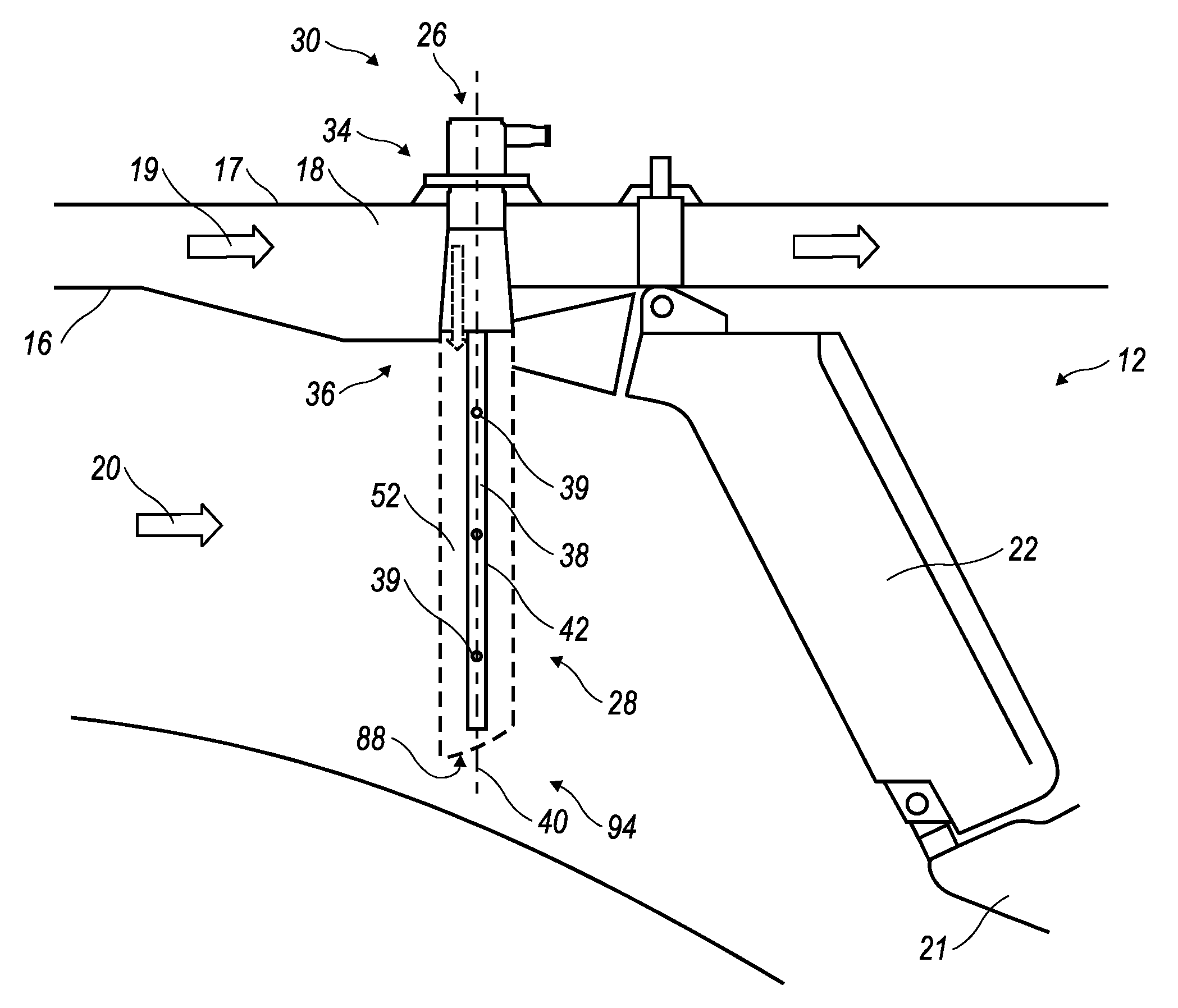
[0042] Exemplary embodiments of the present invention are depicted in the accompanying drawings; the primary and unique common component being the configuration and orientation of an elongate fuel spraybar 28 for a turbo-combustion engine 12, which is contemplated to take the form of either a turbo-jet or turbo-fan configuration.

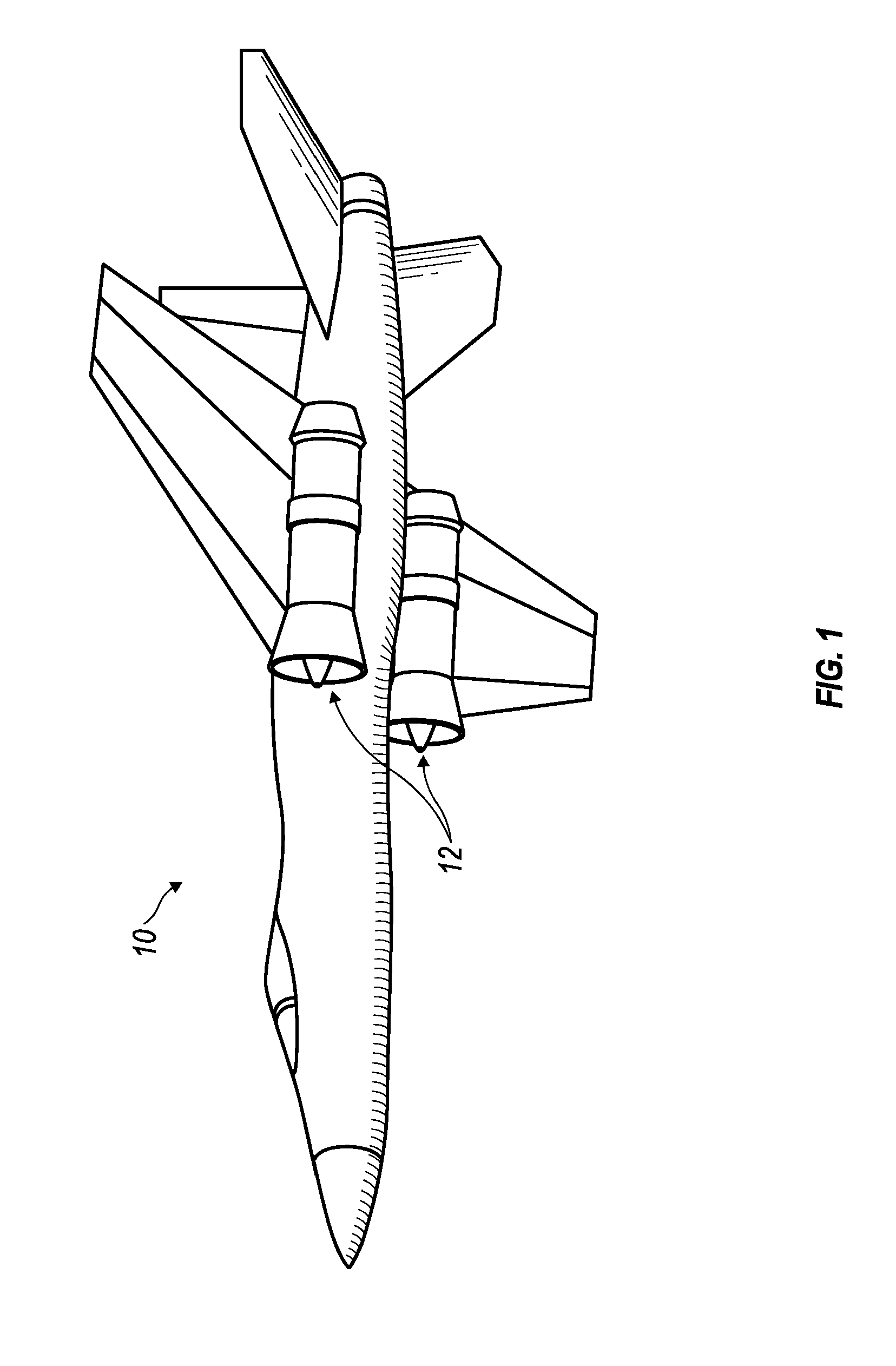
[0043]FIG. 1 illustrates an actual utilization embodiment of the invention wherein an aircraft 10 is shown with a pair of turbo-combustion engines 12 mounted thereupon.

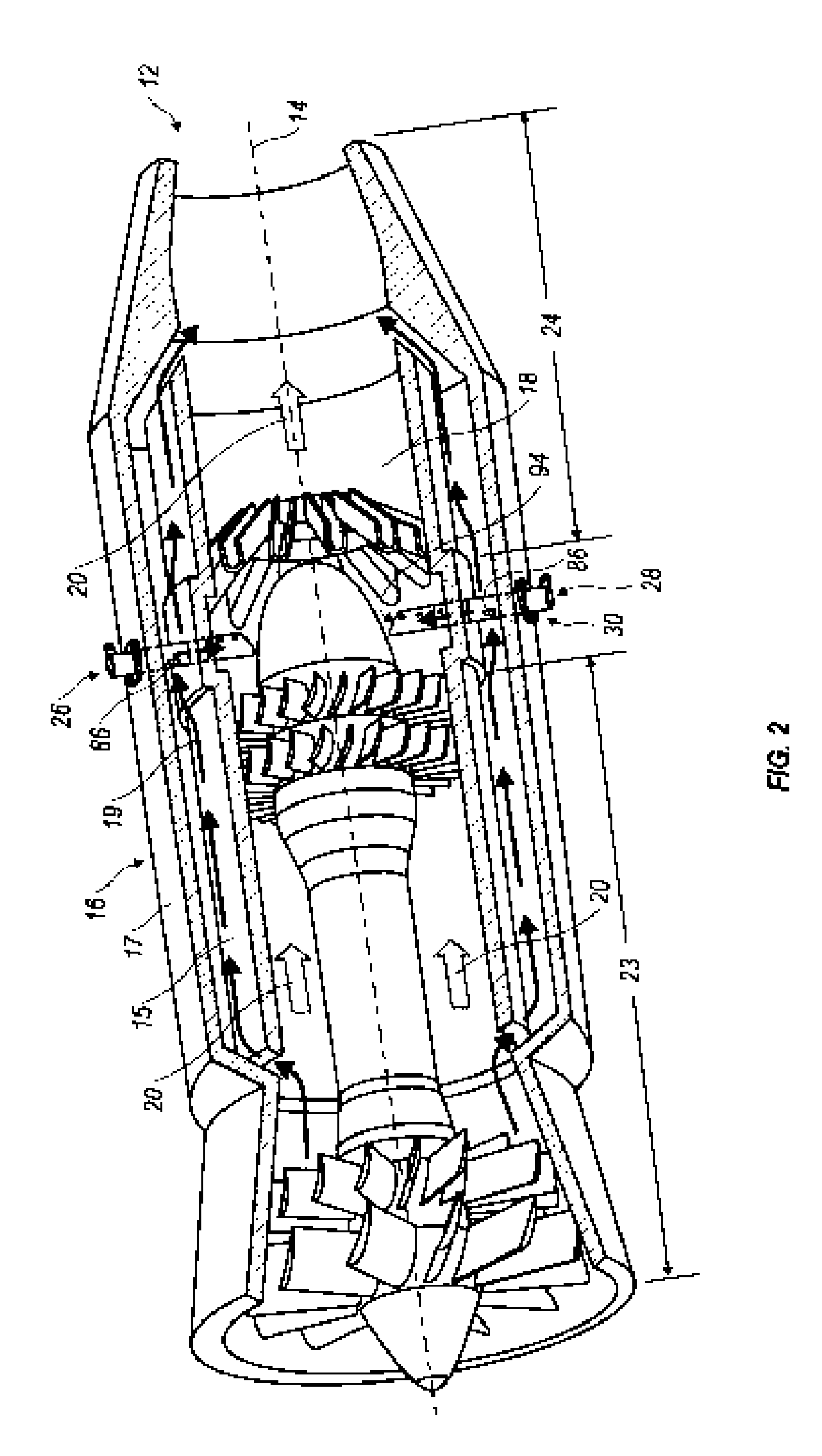
[0044]FIG. 2 illustrates in detail, one of the engines 12 depicted as being mounted on the aircraft 10 in FIG. 1. In FIG. 2, the engine 12 is shown having a longitudinal axis 14 centrally located through a casing 16 of the engine 12. Defined within the casing 16 is an interior through-core 18 which is generally divided into a gas turbine section 23 preceding an afterburner section 24. Through the core 18, and the turbine and afterburner sections 23, 24, a core gas flow 20 passes.

[0045] An a...


PUM


Abstract

Method and apparatus for providing an afterburner fuel-feed arrangement including an elongate fuel spraybar for distributing fuel to the afterburner section of a turbo-combustion engine. The spraybar has a longitudinal axis and includes a fuel-receiving spray head in fluid communication with a plurality of elongate fuel pipes surrounded by an elongate, aerodynamic-shaped shroud. The spray head is configured to be mounted in a casing of a turbo-combustion engine which projects the surrounded fuel pipes into an interior through-core of the engine in cross-wise orientation to a core gas flow thereof. The shroud has an interior lateral sidewall that includes a pipe-receiving portion configured to abuttingly engage a corresponding shroud-engaging portion of an exterior surface of one of the fuel pipes. The pipe-receiving portion is configured to substantially radially fix a fuel pipe, received therein, relative to the shroud. In this manner, the fuel pipes are supported along their length, and when the pipes are abuttingly engaged with the shroud, the braced configuration is stiffened which raises the eigenfrequencies of the assembly into ranges higher than those of the incorporating engine.

Description

CROSS-REFERENCE TO RELATED APPLICATIONS [0001] The present application claims the benefit of U.S. Provisional Application Nos. 60 / 601,011 filed 12 Aug. 2004 and 60 / 522,205 filed 31 Aug. 2004. Said applications are incorporated herein by reference in their entireties.FIELD OF THE INVENTION [0002] The present invention relates generally to afterburners for jet engines; and more particularly, the invention relates to afterburner fuel-feed arrangements for such engines which may be exemplarily employed on aircraft. BACKGROUND OF THE INVENTION [0003] Afterburner spraybars for jet engines are well appreciated assemblies by those persons skilled in the relevant art. An example of such spraybars is found in International Publication Number WO 2004 / 033966 A1 which designates the United States, and in the corresponding United States Provisional Patent Application having Application No. 60 / 319,601; each of which are hereby expressly incorporated by reference for purposes of disclosure. [0004] ...

Claims


Application Information

Patent Timeline
Patent Type & Authority Applications(United States)
IPC IPC(8): F02K3/10
CPCF02C7/222F23R3/20F02K3/10
Inventor ANDERSSON, STEFANBACKANDER, PATRIKFALK, HANSLINDBLAD, KLASSCHMIDT, HAKAN
Owner VOLVO AERO CORP
Why Eureka
Try Eureka