Synchronous electric machine

a technology of synchronous electric machines and electric motors, applied in the direction of dynamo-electric machines, magnetic circuit rotating parts, magnetic circuit shapes/forms/construction, etc., can solve the problems of not decreasing vibration or high, and achieve the effect of reducing electromagnetic excitation for

Active Publication Date: 2005-09-15
NISSAN MOTOR CO LTD
View PDF5 Cites 12 Cited by
  • Summary
  • Abstract
  • Description
  • Claims
  • Application Information

AI Technical Summary

Benefits of technology

[0007] According to a first aspect of the present invention there is provided a synchronous electric machine comprising: a stator provided with teeth wound around by windings that is capable of generating electromagnetic fields; and a rotor that is provided with permanent magnets generating magnetic fields and capable of rotating by interaction of th

Problems solved by technology

The above known conventional synchronous electric machine, however, encounters a problem that it can not decrease vibration or

Method used


Image

  • Synchronous electric machine
  • Synchronous electric machine
  • Synchronous electric machine

Examples


first embodiment

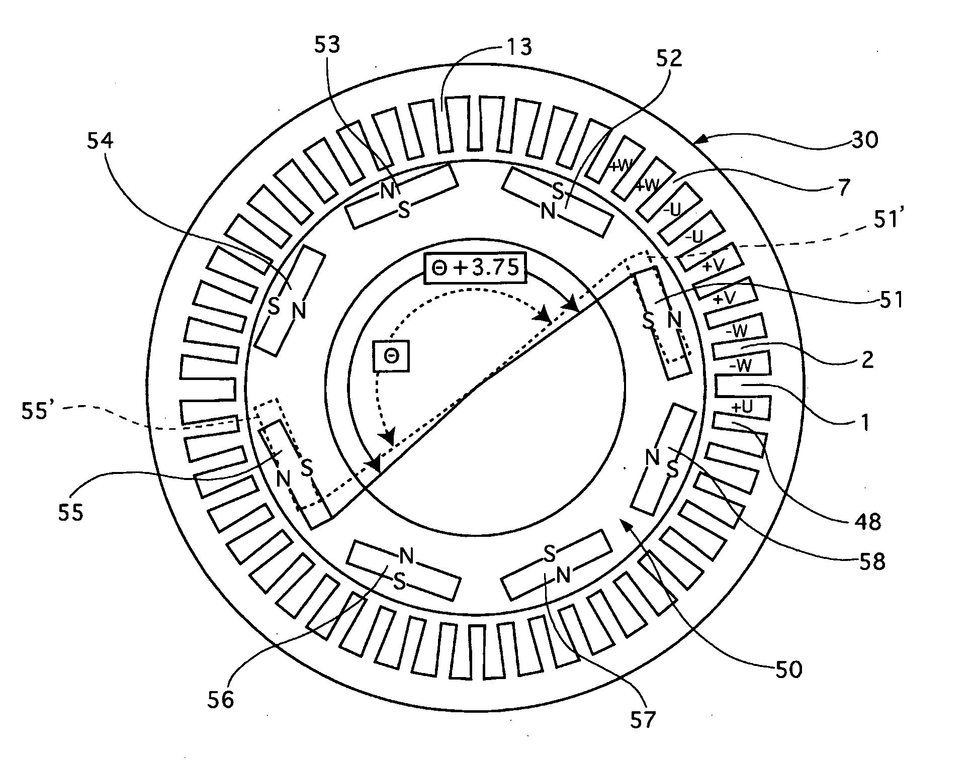
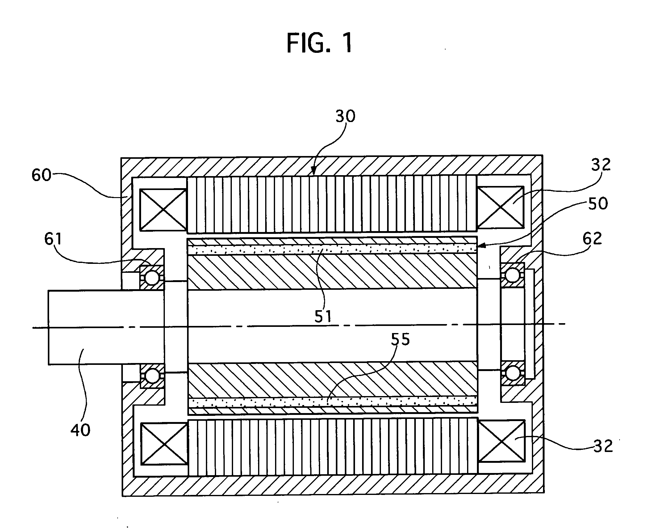
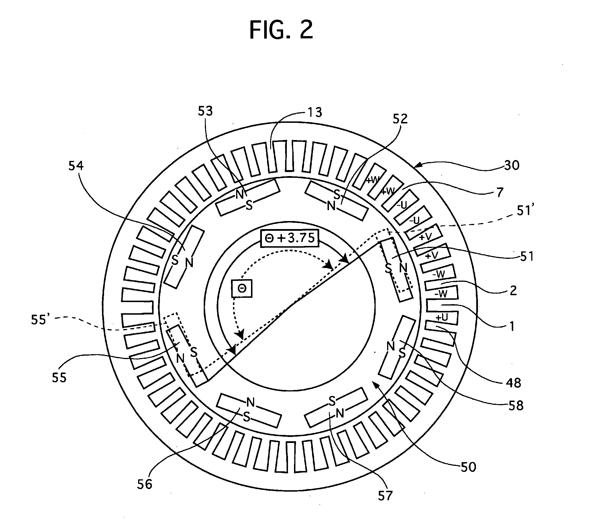
[0024] Referring to FIGS. 1 and 2 of the drawings, there is shown a first preferred embodiment of a synchronous electric machine according to the present invention. FIG. 1 shows a longitudinal sectional view of the electric machine of the first embodiment, and FIG. 2 shows a cross sectional view of a stator and a rotor used in the electric machine shown in FIG. 1.

[0025] The synchronous electric machine of this embodiment is a synchronous three-phase motor having four pole pairs and distributed windings wound around forty eight stator teeth, which tends to be in wide usage because of its high output power and low vibration. The machine has a stator 30, a rotor 50 rotatable in the stator 30, and a motor case 60 containing the stator 30 and the rotor 50.

[0026] The stator 30 is made up of laminated steel sheets that are integrally formed to be in a circular cylinder shape having forty eight teeth 1 to 48 at its inner portion facing an outer surface of the rotor 50. Forty eight slots ar...

second embodiment

[0046] A synchronous electric machine according to the present invention will be described with reference to the accompanying drawings of FIGS. 11 to 13.

[0047] In this electric motor of the second embodiment, plural pairs of magnets are dislocated from positions where they are placed at an even pitch.

[0048]FIG. 11 shows a cross sectional view of a quarter of a stator 30 and a rotor 50 of the electric machine of the second embodiment, where a pair of magnets 51 and 52 in the same pole pair is set so that they are located to have the angle Θ+3.75 degrees (Θ=45 degrees in this case) therebetween: the magnets 51 and 52 are displaced by 3.75 degrees from positions where they are positioned at the even pitch. In addition, a pair of magnets 53 and 54, a pair of magnets 55 and 56, and a pair of magnets 57 and 58, which are not shown but correspond to the magnets shown in FIG. 2, are dislocated by +3.75 degrees to be a symmetric relation with one another with respect to 0 degree and 90 degr...


PUM


Abstract

A synchronous electric machine includes a stator and a rotor. The stator is provided with teeth, which are wound around to establish electromagnetic fields. The rotor is provided with permanent magnets to generate magnetic fields, so that the rotor can rotate by interaction of the magnetic fields of the windings and the permanent magnets of the magnets. At least one pair of the permanent magnets is dislocated by a predetermined angle from positions where the permanent magnets is arranged at even pitch, and the predetermined angle being set to reduce electromagnetic excitation force acting on said teeth.

Description

BACKGROUND OF THE INVENTION [0001] 1. Field of the Invention [0002] The present invention relates to a synchronous electric machine having a stator with windings and a rotor with permanent magnets so that the rotor can be rotatable in the stator by mutual interaction between electromagnetic fields of the windings and magnetic fields of the permanent magnets. [0003] 2. Description of the Related Art [0004] A synchronous electric machine of this kind is disclosed in Japanese patent laying-open publication No. Hei 07-255159. This electric machine acts as an electric motor and includes a rotor with permanent magnets to generate magnetic fields and a stator with windings to establish electromagnetic fields. The magnets are arranged at an uneven pitch along a circumference of the rotor so that the magnets are dislocated forward and backward by 30 degrees in an electric angle from the positions where they are placed at an even pitch. Specifically, the number of pole pairs is set to be even...

Claims


Application Information

Patent Timeline
IPC IPC(8): H02K1/27H02K21/12H02K21/14H02K37/00
CPCH02K1/276H02K2213/03H02K29/03H02K21/16
Inventor YASHIRO, HARUKITOUJIMA, HISAAKIOOKI, KAZUHIRO
Owner NISSAN MOTOR CO LTD
Why Eureka
Try Eureka