

Controller for ac rotary electric machine
A technology of rotating electrical machine and control device, which is applied in the direction of AC motor control, motor generator control, control of electromechanical transmission device, etc. Vibration effect
- Summary
- Abstract
- Description
- Claims
- Application Information
AI Technical Summary
Problems solved by technology
Method used
Image

Examples
Embodiment approach 1
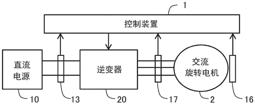
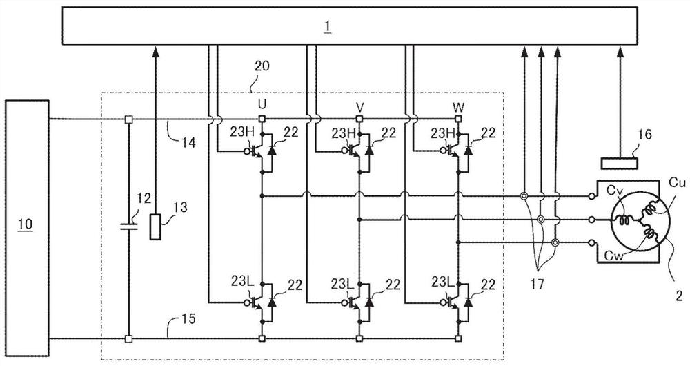
[0043] A control device 1 for an AC rotating electrical machine (hereinafter simply referred to as a control device 1 ) according to Embodiment 1 will be described with reference to the drawings. figure 1 and figure 2 It is a schematic configuration diagram of the AC rotating electrical machine 2 and the control device 1 according to the present embodiment.
[0044] 1-1. AC rotary motor
[0045] The AC rotating electric machine 2 has a stator provided with windings of a plurality of phases and a rotor provided with magnets. In the present embodiment, three-phase windings Cu, Cv, and Cw of U-phase, V-phase, and W-phase are provided. The 3-phase windings Cu, Cv, and Cw are star-connected. In addition, 3-phase windings can also be connected in delta. The AC rotating electrical machine 2 is a permanent magnet type synchronous rotating electrical machine, and a permanent magnet is provided in a rotor. In this embodiment, permanent magnets are embedded inside the magnetic stee...
Embodiment approach 2
[0113] The AC rotating electric machine 2 and the control device 1 according to Embodiment 2 will be described. The description of the same structural parts as those in the first embodiment described above is omitted. The basic configurations of the AC rotating electric machine 2 and the control device 1 of this embodiment are the same as those of Embodiment 1, but differ from Embodiment 1 in that a DC booster 40 is provided, and in the voltage increase mode, the DC voltage Vdc is changed by DC booster 40 boosts the voltage. Figure 14 It is a schematic configuration diagram of the AC rotating electrical machine 2 and the control device 1 according to the present embodiment.
[0114] A DC booster 40 for boosting the DC voltage Vdc is provided between the DC power supply 10 and the inverter 20 . A DC-DC converter such as a step-up chopper circuit is used as the DC booster 40 to boost the DC voltage output from the DC power supply 10 and supply it to the inverter 20 .
[0115...
Embodiment approach 3
[0126] The AC rotating electrical machine 2 and the control device 1 according to Embodiment 3 will be described. The description of the same structural parts as those in the first embodiment described above is omitted. The basic structure of the AC rotating electrical machine 2 and the control device 1 of this embodiment is the same as that of Embodiment 1, but the difference from Embodiment 1 is that it has an AC booster 50, and in the voltage increase mode, the AC booster The converter 50 boosts the voltage applied to the three-phase winding. Figure 16 It is a schematic configuration diagram of the AC rotating electrical machine 2 and the control device 1 according to the present embodiment.
[0127] An AC booster 50 for boosting the AC applied voltage of each phase is provided between the inverter 20 and the three-phase windings of the AC rotating electrical machine 2 . For example, a wiper resistor regulator capable of changing the boost rate is used for the AC booster...
PUM
 Abstract
Description
Claims
Application Information