Matching feed partially inside a waveguide ridge

Inactive Publication Date: 2005-09-15
THE UNITED STATES OF AMERICA AS REPRESENTED BY THE SECRETARY OF THE NAVY
View PDF1 Cites 12 Cited by
  • Summary
  • Abstract
  • Description
  • Claims
  • Application Information

AI Technical Summary

Benefits of technology

[0008] The impedance matching feed comprising the present invention overcomes some of the difficulties of the past including those mentioned above in that it is a relatively simple in design, yet highly effective for matching the input transmission line impedance, which is generally fifty ohms, to the waveguide impedance. The impedance of the ridge waveguide is an arbitrary impedance, that is it will generally be different than the impedance of the coaxial transmission line.

Problems solved by technology

The probe heights of the type illustrated in U.S. Pat. No. 5,867,073 and in other simple probe transition feeds are generally dimensionally sensitive and often impractical in ridge waveguides when the space from the top of the ridge to the top or upper face of the waveguide is relatively small.

Method used


Image

  • Matching feed partially inside a waveguide ridge
  • Matching feed partially inside a waveguide ridge
  • Matching feed partially inside a waveguide ridge

Examples


Embodiment Construction

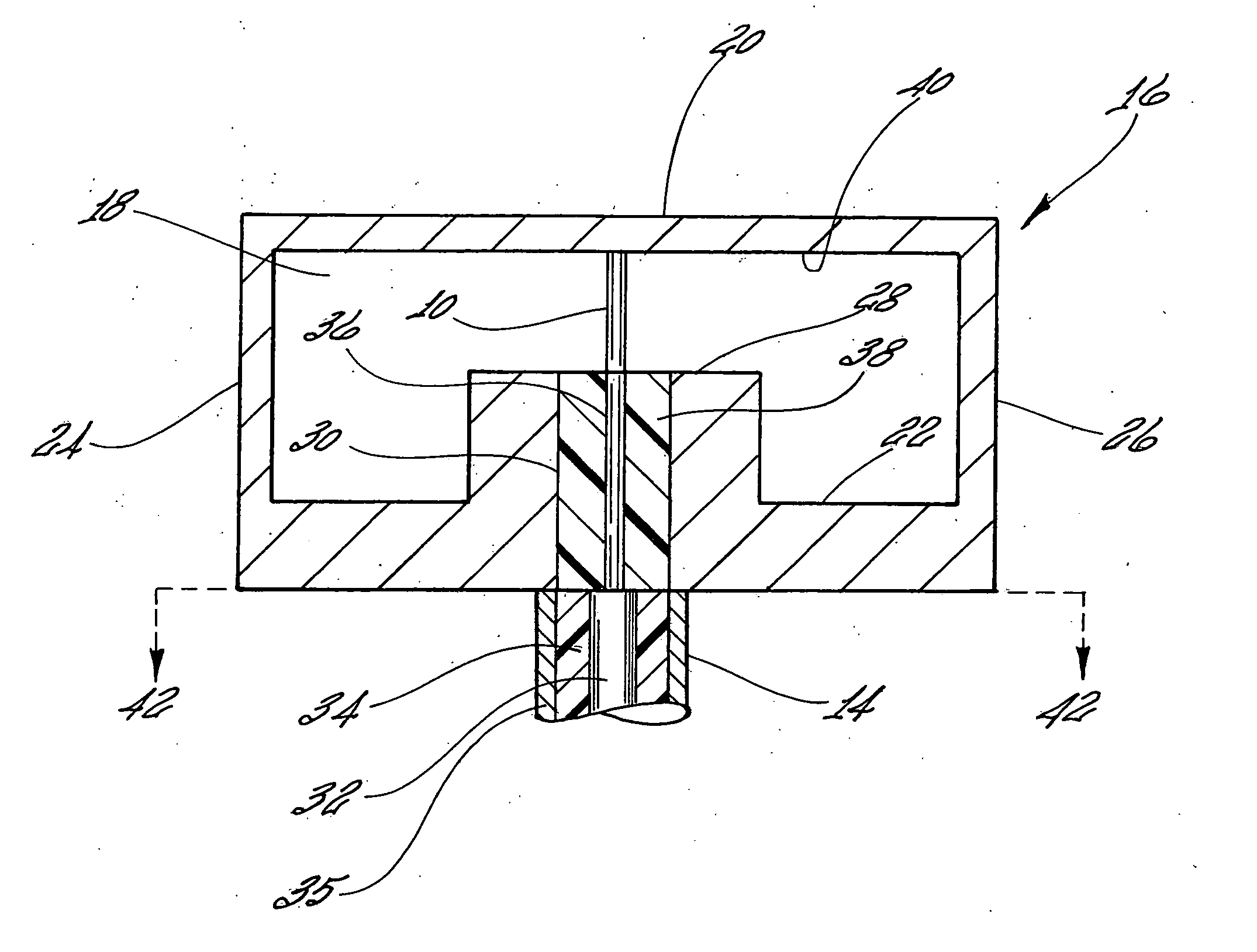
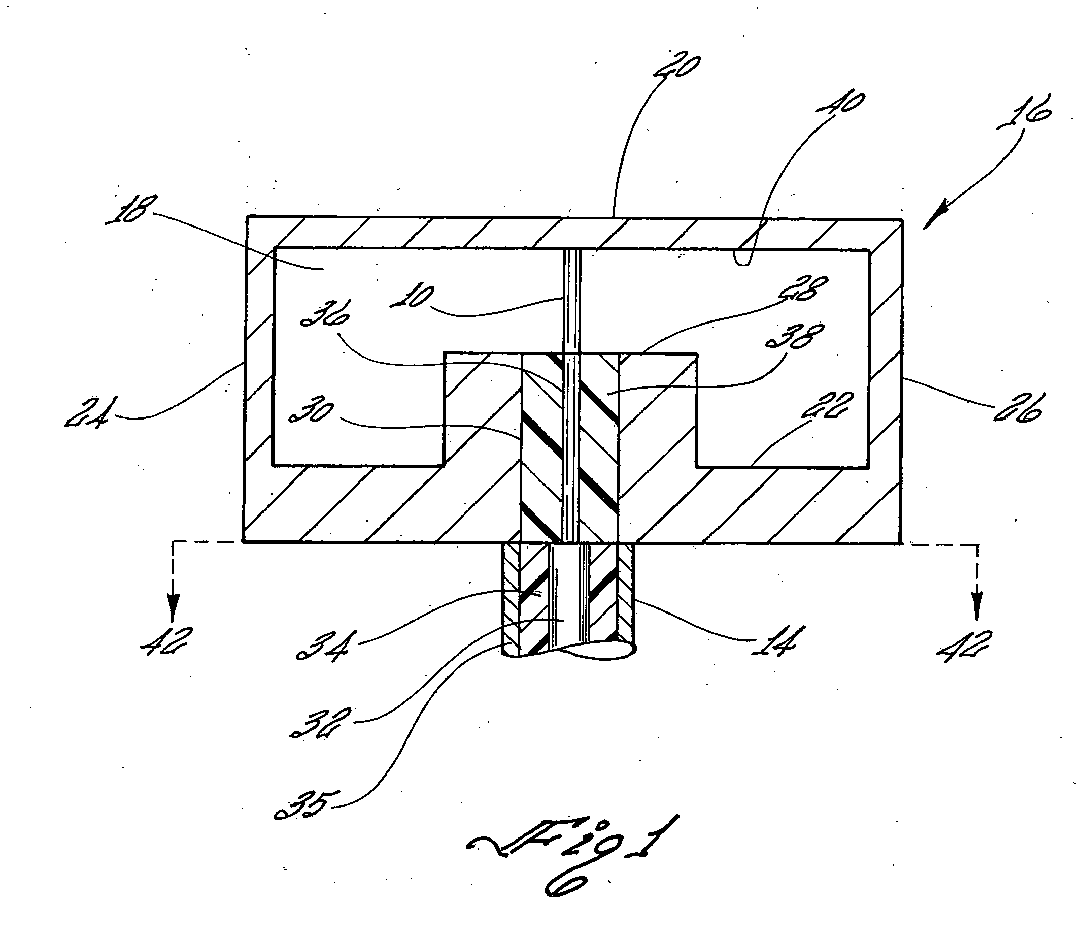
[0014] Referring first to FIG. 1, there is shown a probe 10 which couples a coaxial transmission line 14, which is generally a connector, to a hollow metallic waveguide 16. As depicted in FIG. 1, coaxial transmission line 14 is mounted on the bottom surface of waveguide 16. The waveguide 16 may also be a dielectric filled metallic waveguide.

[0015] The waveguide 16 is formed of a hollow interior 18 with open ends to receive and deliver radio frequency signals. Waveguide 16, which has a rectangular shape, includes an upper or top wall 20, a lower or bottom wall 22 and a pair of side walls 24 and 26. A ridge 28, which is located at or near the center of the waveguide 16, runs the length of waveguide 16, and extends vertically upward from bottom or lower wall 22 of the waveguide 16. One end of the waveguide 16 is terminated with a quarterwave choke, which is a short approximately λg / 4.

[0016] A transformer 30 located within ridge 28 electrically connects the probe 10 to the coaxial tra...


PUM


Abstract

An impedance matching feed is disclosed for use in a ridge waveguide which allows a coaxial transmission line, generally having an impedance of fifty ohm, to be matched to a ridge waveguide of arbitrary impedance. The matching feed consist of a transformer which is located inside the ridge of the waveguide, a probe and a quarter wave choke.

Description

BACKGROUND OF THE INVENTION [0001] 1. Field of the Invention [0002] The present invention relates generally to a ridge waveguide. More specifically, the present invention relates to a ridge waveguide resistive type feed with a matching transformer within the ridge of the waveguide which matches a standard coaxial transmission line to a ridge waveguide. [0003] 2. Description of the Prior Art [0004] Typically, in a simple transition feed for a waveguide the probe does not touch the upper surface and may require additional elements for impedance matching. One such probe design that extends partially into the waveguide is illustrated in U.S. Pat. No. 5,867,073, to Sander Weinreb and Dean Bowyer which issued Feb. 2, 1999. Disclosed in U.S. Pat. No. 5,867,073 is a transition between a waveguide and a transmission line in which a probe portion of the transmission line extends into the waveguide to electrically field couple signals between the waveguide and transmission line. The transmissi...

Claims


Application Information

Patent Timeline
IPC IPC(8): H01P5/103
CPCH01P5/103
Inventor FREEMAN, WILL
Owner THE UNITED STATES OF AMERICA AS REPRESENTED BY THE SECRETARY OF THE NAVY
Why Eureka
Try Eureka