Zoom lens
a zoom lens and zoom technology, applied in the field of zoom lenses, can solve the problems of generating aberration asymmetrical with respect to the co-axis, requiring a large space to arrange the moving mechanism, and a general complex moving mechanism
- Summary
- Abstract
- Description
- Claims
- Application Information
AI Technical Summary
Benefits of technology
Problems solved by technology
Method used
Image
Examples
embodiment 1
Exemplified Embodiment 1
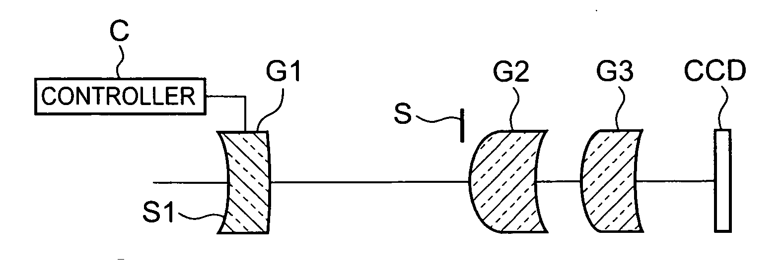
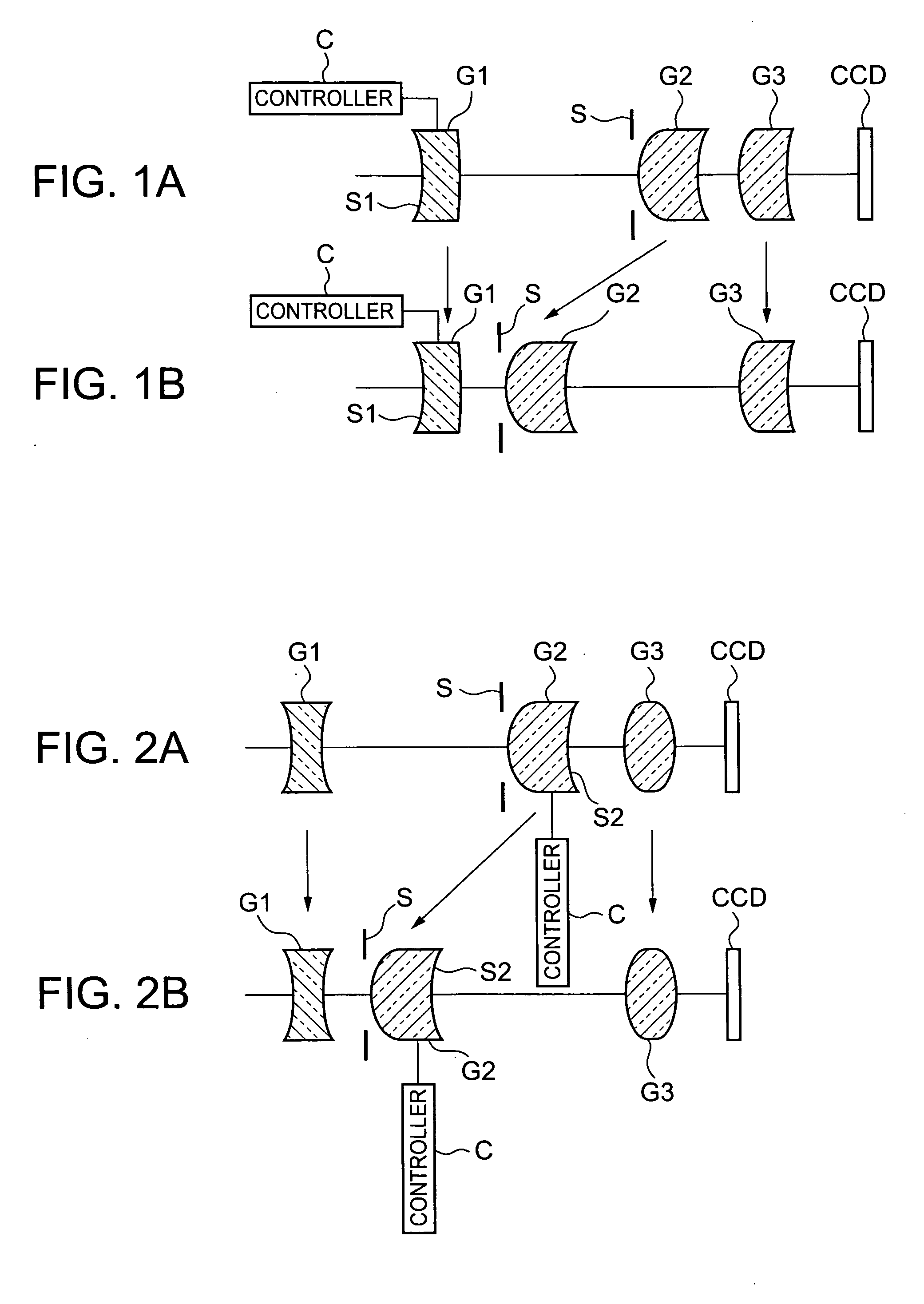
[0083] Exemplified embodiment 1 to be described below corresponds to the zoom lens according to the above-described first embodiment.
[0084] More specifically, the focal lengths, principal points, and principal point intervals of the respective groups, the group intervals, the focal length of the entire system, and the total length at object distance T=∞ of the zoom lens are shown in Table 1. The focal lengths, principal points, and principal point intervals of the first lens group serving as a refractive power variable element at the short and long focal length ends at object distance T=250 mm are shown in Table 2. The object distance indicates the distance from the object to the surface apex of the zoom lens closest to the object. For HF, HR, and HD in the tables, the direction from the object to the image is defined as positive.
TABLE 1(Short Focal Length End: W) T = ∞First GroupP1 (W) = −0.082HF1 (W) = 0.596HR1 (W) = 5.707HD1 (W) = 1.198D1 (W) = 9.254Sec...
embodiment 2
Exemplified Embodiment 2
[0088] Exemplified embodiment 2 to be described below corresponds to the zoom lens according to the above-described second embodiment.
[0089] More specifically, the focal lengths, principal points, and principal point intervals of the respective groups, the group intervals, the focal length of the entire system, and the total length at object distance T=∞ of the zoom lens are shown in Table 3. The focal lengths, principal points, and principal point intervals of the second lens group serving as a refractive power variable element at the short and long focal length ends at object distance T=250 mm are shown in Table 4. The object distance indicates the distance from the object to the surface apex of the zoom lens closest to the object. For HF, HR, and HD in the tables, the direction from the object to the image is defined as positive.
TABLE 3(Short Focal Length End: W) T = ∞First GroupP1 (W) = −0.111HF1 (W) = −1.062HR1 (W) = 1.030H01 (W) = 0.937D1 (W) = 6.552...
embodiment 3
Exemplified Embodiment 3
[0148] The exemplified embodiment 3 which will be explained hereinafter concerns the zoom lens in the third embodiment. Data of the zoom lens in this exemplified embodiment 3 is listed in table 5, and radii R5 of curvature at a short focal distance end, an intermediate focal distance and a long focal distance end with an object distance T=∞, inter-surface spaces D4, D5 and F as F-number, a focal distance f of an entire image pick-up lens system and a viewing angle 2ω are listed in table 6. Further, aspheric data are listed in table 7, and further, radii R5 of curvature at a short focal distance end and a long focal distance end with an object distance T=250 mm, and inter-surface spaces D4, D5 are listed in table 8. Further, FIGS. 8A and 8C show aberration charts at a short focal distance (FIG. 8A), at an intermediate focal distance (FIG. 8B) and at a long focal distance (FIG. 8C) with an object distance T=°° in the exemplified embodiment 3. It is noted here t...
PUM
 Abstract
Description
Claims
Application Information
 - R&D
- Intellectual Property
- Life Sciences
- Materials
- Tech Scout
- Unparalleled Data Quality
- Higher Quality Content
- 60% Fewer Hallucinations
Browse by: Latest US Patents, China's latest patents, Technical Efficacy Thesaurus, Application Domain, Technology Topic, Popular Technical Reports.
© 2025 PatSnap. All rights reserved.Legal|Privacy policy|Modern Slavery Act Transparency Statement|Sitemap|About US| Contact US: help@patsnap.com


