Method and system for processing an image

a processing method and image technology, applied in the field of image processing methods and image processing systems, can solve problems such as wrong diagnosis and reduction in diagnosis reliability

Inactive Publication Date: 2005-09-15
CANON KK
View PDF6 Cites 14 Cited by
  • Summary
  • Abstract
  • Description
  • Claims
  • Application Information

AI Technical Summary

Problems solved by technology

This can cause wrong diagnosis unless information is provided to indicate that there is the diseased part.
However, in the conventional technique, past diagnosis information of a patient is not used in the temporal difference determination process, which can cause a reduction in reliability of diagnosis.

Method used


Image

  • Method and system for processing an image
  • Method and system for processing an image
  • Method and system for processing an image

Examples


first embodiment

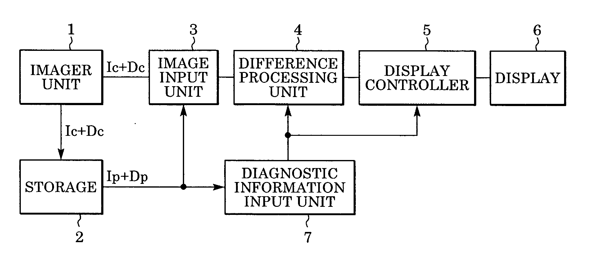
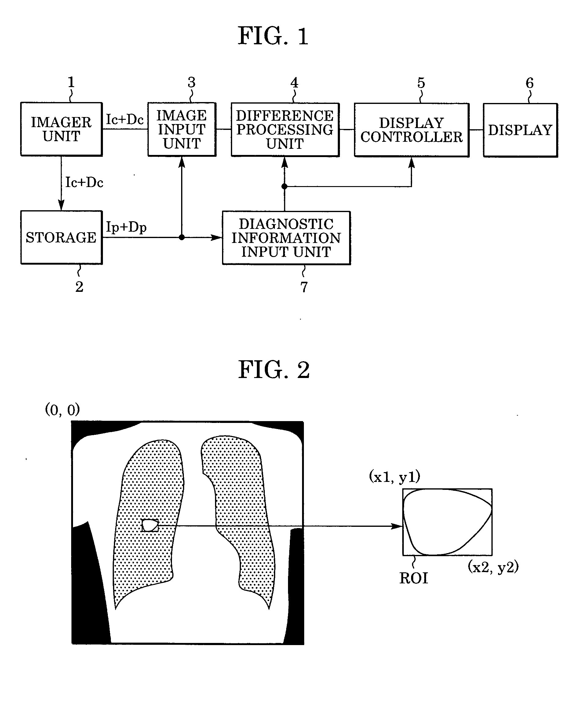
[0029]FIG. 1 is a circuit block diagram of an image processing system according to a first embodiment. The output of the imager unit 1 for capturing a medical image is connected to a storage unit 2 that includes a hard disk or a magnetooptical disk for storing images. The imager unit 1 is also connected to an image input unit 3. The output of the image input unit 3 is connected to a difference processing unit 4, whose output is connected to a display controller 5. The output of the display controller 5 is connected to a display 6 such as a CRT monitor or a liquid crystal display or a printer. The output of the storage unit 2 is connected to the image input unit 3 and a diagnostic information input unit 7. The output of the diagnostic information input unit 7 is connected to the difference processing unit 4 and the display controller 5.

[0030] The imager unit 1 produces an image used in diagnosis. For example, a modality such as an X-ray imager is used as the imager unit 1. Although ...

second embodiment

[0048] In the first embodiment described above, weighting factors used in the determination of shift vectors by using matching are determined based on the region of interest defined in the past diagnosis information. Instead of adjusting the weighting factor, the matching process may be switched.

[0049] In a second embodiment described below, in view of the above, a plurality of matching methods are prepared for use in the matching process between the current image Ic and the past image Ip. More specifically, the matching process is performed every predetermined number of pixels, and the predetermined number is switched. When the cross-correlation coefficient is used as the matching measure, the cross-correlation coefficient C(a, b) at a point (a, b) is given by equation (3) shown below. C⁡(a,b)=∑m=0M-1⁢ ⁢∑n=0N-1⁢{Ip⁡(a,b)⁡(m,n)-I_p}⁢{Ic⁡(m,n)-I_c}σp⁢σc(3)I-p=1MN⁢∑m=0M-1⁢ ⁢∑n=0N-1⁢Ip⁡(a,b)⁡(m,n)(4)I-c=1MN⁢∑m=0M-1⁢ ⁢∑n=0N-1⁢Ic⁡(m,n)(5)σp=1MN⁢∑m=0M-1⁢ ⁢∑n=0N-1⁢{Ip⁡(a,b)⁡(m,n)-I-p}2(6...

third embodiment

[0053] In the first and second embodiments described above, the process is adapted depending on the region of interest defined in the past diagnosis information. Alternatively, the process may be adapted based on other information.

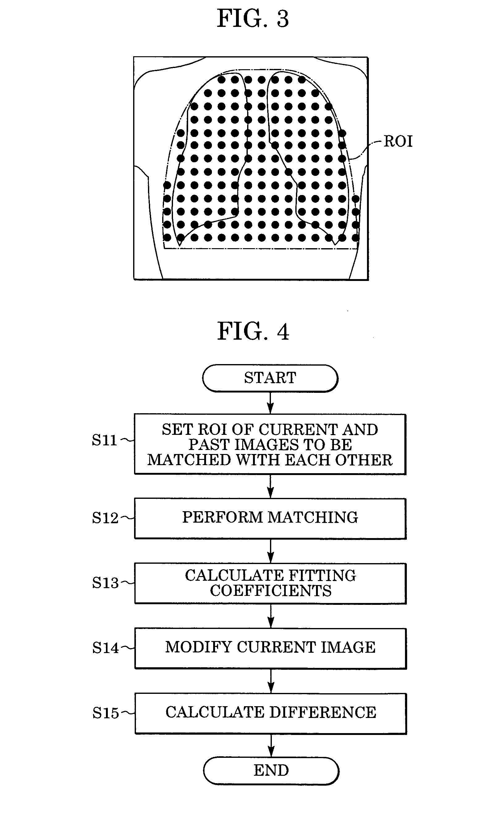
[0054]FIG. 5 is a flow chart showing a difference determination process according to a third embodiment. Steps S11 to S15 are similar to those shown in FIG. 4. In step S16 and following steps, the image quality of a difference image produced via steps S11 to S15 is evaluated as follows.

[0055] That is, in step S16, a sample region is defined in a part corresponding to a lung window in the difference image. In an example shown in FIG. 6A, two sample regions ROIsr and ROIsl are defined in a difference image. These two sample regions are set at the center of a lung window extracted from the past image Ip. The extraction of the lung window can be performed using a known method, and thus a further detail description thereof is not given herein.

[0056] Although...


PUM


Abstract

In computer aided diagnosis, a high-accuracy image indicating a temporal difference of a diseased part of a patient is produced from a current image and a past image as follows. First, a plurality of matching ROIs (Regions of Interest) are defined on the current image and the past image. A matching processing is performed on corresponding ROIs of the two images to determine points on the past image corresponding to the respective points on the current image. Obtained shift vectors are fitted to a two-dimensional polynomial. In the fitting, when a matching ROI of the current image is included in or overlapped with a previously-defined region of interest, shift vectors are weighted by a small factor. The current image is then modified according to obtained fitting coefficients. Finally, an image indicating the difference between the modified current image and the past image is produced.

Description

BACKGROUND OF THE INVENTION [0001] 1. Field of the Invention [0002] The present invention relates to an image processing method and an image processing system for extracting a temporal change in a subject based on images such as X-ray images of the subject. [0003] 2. Description of the Related Art [0004] In the field of medical image technology, intensive research activities continue to occur on computer aided diagnosis (CAD). In CAD, a diseased part of a patient is detected by analyzing a diagnosis image such as an X-ray image or a CT (Computer Tomography) image using a computer. CAD is a promising technique for early disease detection. [0005] A wide variety of CAD techniques have been proposed depending on what is detected and on what type of image is output. Of the wide variety of techniques, one promising technique is known as temporal difference CAD. In this technique, a difference between images of the same subject taken at different times is detected, and an image is produced...

Claims


Application Information

Patent Timeline
Patent Type & Authority Applications(United States)
IPC IPC(8): A61B8/00G06K9/00G06T5/50G06T7/00
CPCG06T5/50G06T7/0026G06T2207/30096G06T2207/10116G06T2207/30061G06T2207/10081G06T7/32
Inventor SATO, MAKOTOGUO, MULING
Owner CANON KK
Why Eureka
Try Eureka