Wire dot printer head and wire dot printer

a printer head and wire technology, applied in printing, instruments, ticket-issuers, etc., can solve the problems of high-speed printing, high-speed printing is impossible, and hinder the urging operation of the coil spring, so as to prevent the breakdown of the armature

Active Publication Date: 2005-09-15
TOSHIBA TEC KK
View PDF49 Cites 21 Cited by
  • Summary
  • Abstract
  • Description
  • Claims
  • Application Information

AI Technical Summary

Benefits of technology

[0009] An object of the present invention is to prevent a breakdown of an armature due to a coil spring.

Problems solved by technology

This causes an unstable urging operation of the coil spring 100, resulting in that high-speed printing is impossible.
Further, the broken plastic member hinders the urging operation of the coil spring.
Moreover, the urging operation of the coil spring is not stabilized since it is hindered by the weight of the plastic member, resulting in that high-speed printing is impossible.

Method used


Image

  • Wire dot printer head and wire dot printer
  • Wire dot printer head and wire dot printer
  • Wire dot printer head and wire dot printer

Examples


Embodiment Construction

[0021] Preferred embodiments for carrying out the present invention will be explained with reference to FIGS. 1 to 5.

[Wire Dot Printer Head]

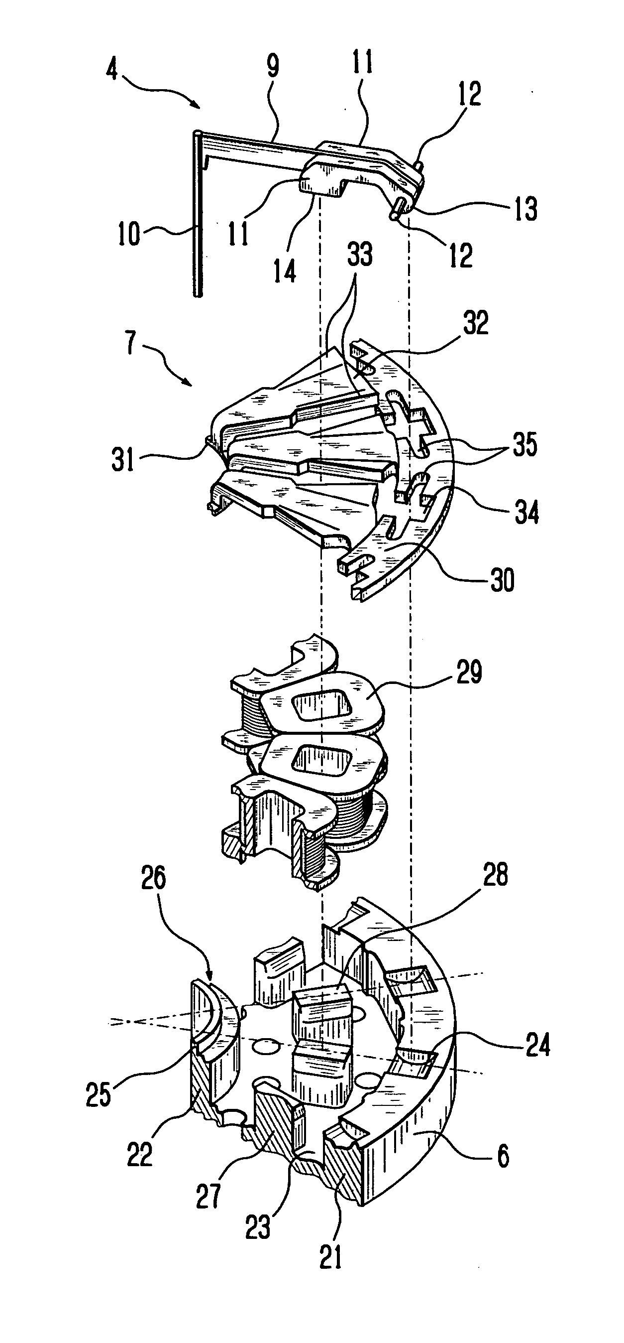
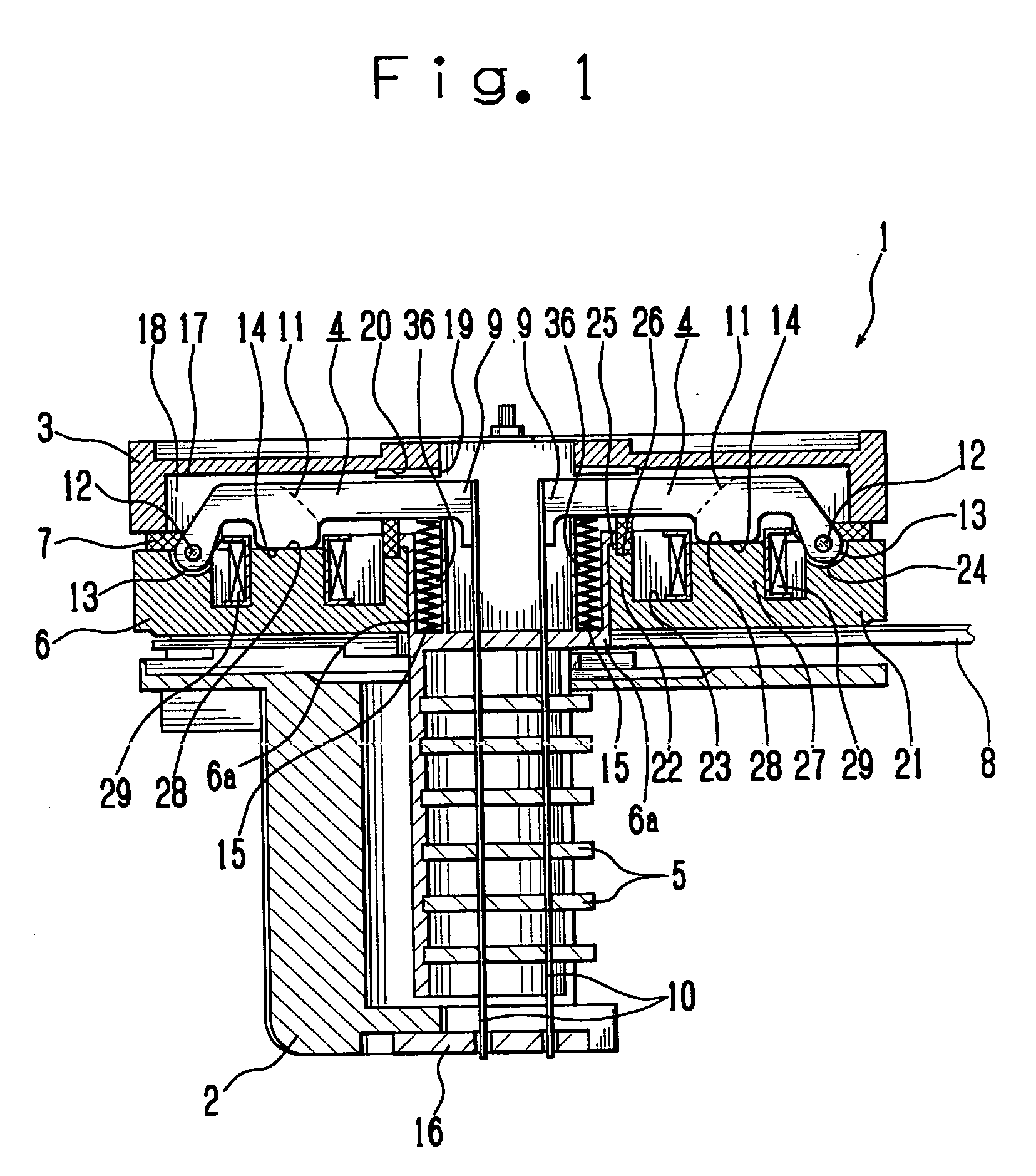
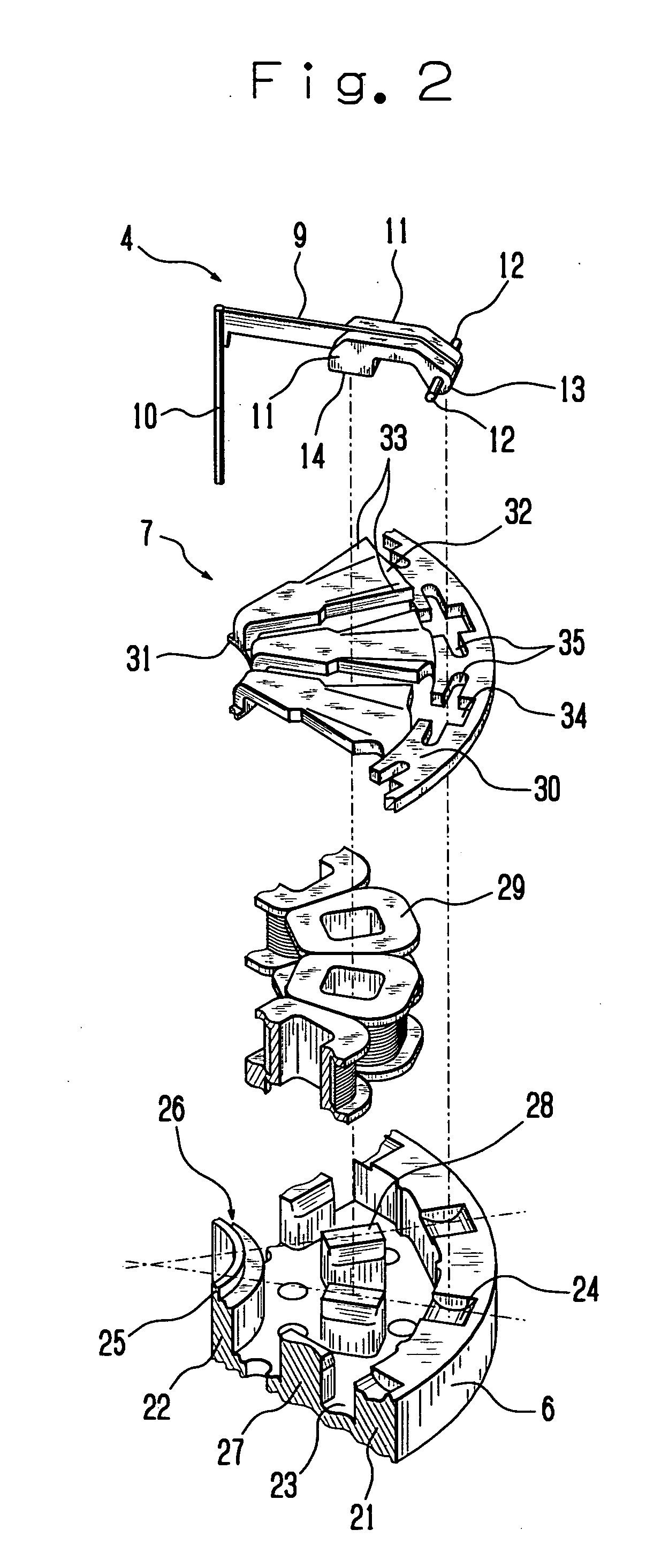
[0022] Firstly, the entire construction of a wire dot printer head 1 will be explained with reference to FIGS. 1 to 4(B). FIG. 1 is a front view in central vertical section schematically showing a wire dot printer head 1 according to the embodiment and FIG. 2 is an exploded perspective view schematically showing a part of the wire dot printer head 1.

[0023] The wire dot printer head 1 has a front case 2 and a rear case 3 coupled together with a mounting screw (not shown). Disposed between the front case 2 and the rear case 3 are armatures 4, wire guides 5, yoke 6, armature spacer 7 and circuit board 8.

[0024] Each of the armatures 4 has an arm 9 that is formed into a plate-like shape and supports a printing wire (hereinafter simply referred to as a wire) 10 at one end thereof in the lengthwise direction (in the direction in which the arm 9 ext...


PUM


Abstract

A wire dot printer head of the present invention has an armature that has an arm supporting a printing wire and pivotably provided at the position opposite to the core, and a coil spring that one end comes in contact with the arm for urging the armature in the direction away from the core, wherein the one end of the coil spring supported by the supporting member is brought into contact with the armature to apply return force to the armature. In order to prevent the breakdown of the armature due to a contact of the coil spring and to realize a stabilized urging operation of the coil spring, a winding end of the coil spring at the one end is located at the position inside of the coil spring and nearer to the supporting member from the contact position where the coil spring comes in contact with the armature.

Description

CROSS REFERENCE TO RELATED APPLICATION [0001] The present application is based on Japanese Priority Document P2004-72634 filed on Mar. 15, 2004, the content of which is incorporated herein by reference. BACKGROUND OF THE INVENTION [0002] 1. Field of the Invention [0003] The present invention relates to a wire dot printer head and a wire dot printer using this wire dot printer head, and more particularly to a wire dot printer head having a structure in which an armature is urged by a coil spring in a direction away from a core and a wire dot printer using this wire dot printer head. [0004] 2. Discussion of the Background [0005] There has been known a wire dot printer head wherein an armature with a printing wire coupled thereto is pivoted between a printing position and a stand-by position, and when the armature is pivoted to the printing position, a tip of the wire is brought into collision with a printing medium to effect printing. In a certain wire dot printer head of this type, t...

Claims


Application Information

Patent Timeline
Patent Type & Authority Applications(United States)
IPC IPC(8): B41J2/275B41J2/27
CPCB41J2/27
Inventor KAWAGUCHI, TAKAHIROTERAO, YASUNOBUTSUCHIYA, KEISHI
Owner TOSHIBA TEC KK
Why Eureka
Try Eureka