Bicycle chain

a technology of bicycle chain and chain, which is applied in the direction of driving chains, chain elements, and portable lifting, etc., can solve the problems of preventing reliable shifting at the rear end of the link plate, and rapid deflection, so as to improve the operation, simplify the chain installation, and increase the strength of the riveted connection

Inactive Publication Date: 2005-09-15
SRAM
View PDF16 Cites 36 Cited by
  • Summary
  • Abstract
  • Description
  • Claims
  • Application Information

AI Technical Summary

Benefits of technology

[0013] During the shifting operation to a larger chainwheel, the outer link plate end that is located at the front in the tension direction is intended to slide past the tooth flank of the first tooth on the large chainwheel, whereas the rear end of the outer link plate needs to brace against the tooth root of the second tooth so that the chain or the next inner link plate is lifted to the level of the chainwheel and the next outer link plate arrives over the corresponding tooth of the larger chainwheel. To improve this operation, the outer link plate is chamfered at the front end facing toward the chainwheel so that it may slide easily along the flank of the first tooth; and the rear end facing toward the chainwheel is not chamfered but rather has a sharp edge so that it may brace against the tooth root of the corresponding tooth in order to raise the level.
[0014] Further, the chamfer at the front end of the outer link plate, facing toward the larger chainwheel, has a positive effect during a shifting operation to the smaller chainwheel. The end of the outer link plate toward the front in the tension direction should not be caught at the tooth root of the corresponding tooth on the larger cha

Problems solved by technology

A disadvantage of the chain disclosed in DE 203 14 167 is that the inner link plate has a wide chamfer in the concave region on an inner edge but not on an outer edge, which may result in rapid deflection at a tangent tooth and prevent riding-up on a toot

Method used


Image

  • Bicycle chain
  • Bicycle chain
  • Bicycle chain

Examples


Embodiment Construction

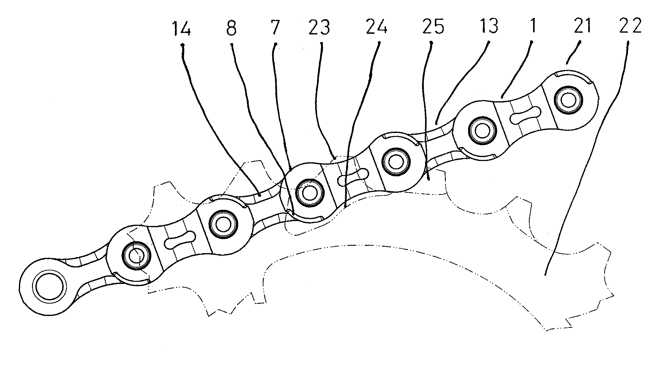
[0025]FIGS. 1-6 illustrate a bicycle drive chain 21 in accordance with one embodiment of the present invention. Looking to FIGS. 5 and 6, the bicycle drive chain 21 includes a plurality of outer link plates 1 and a plurality of inner link plates 13. Pins 18 connect the outer and inner link plates 1, 13 to each other. Chain rollers 20 surround the pins 18.

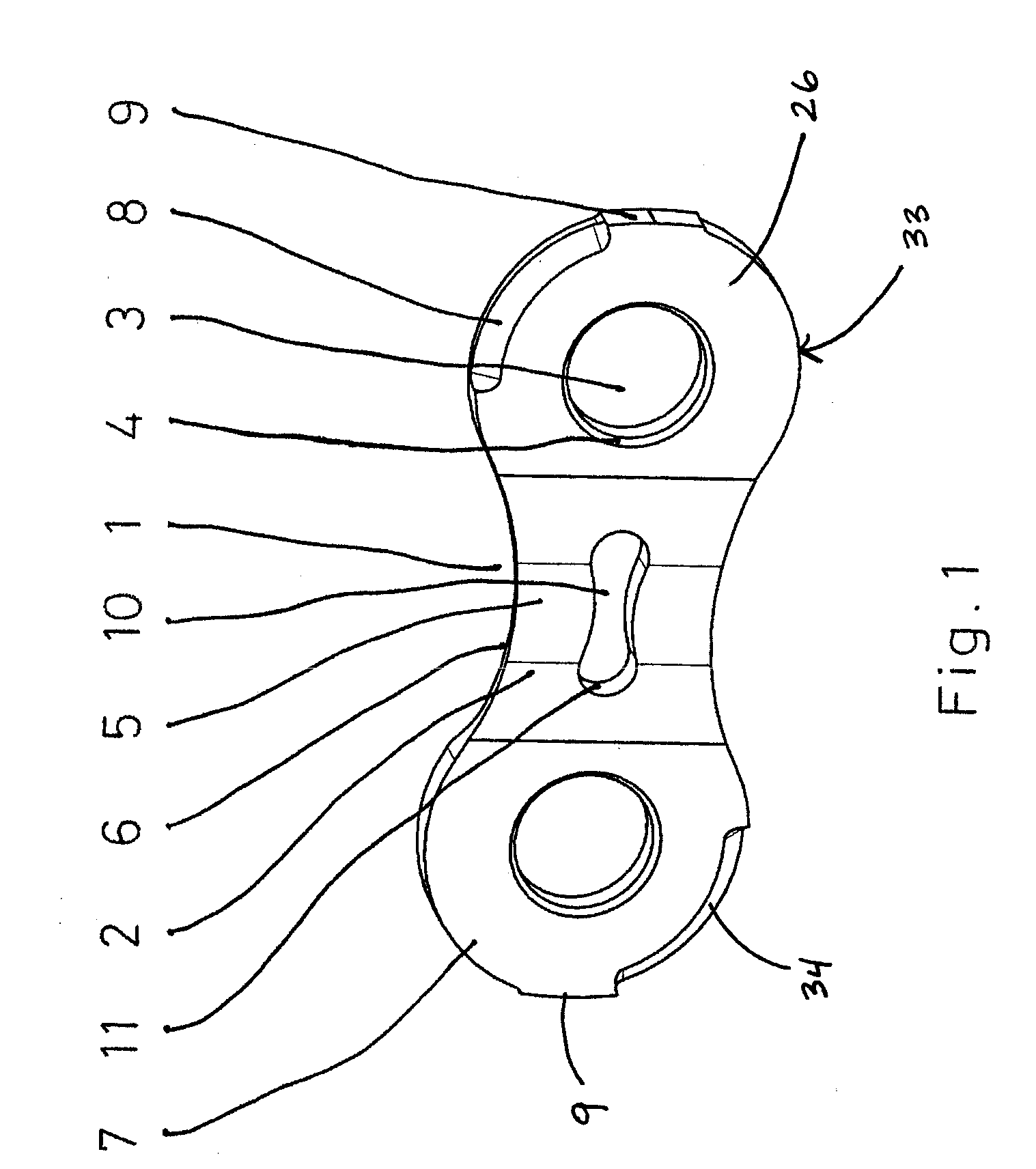
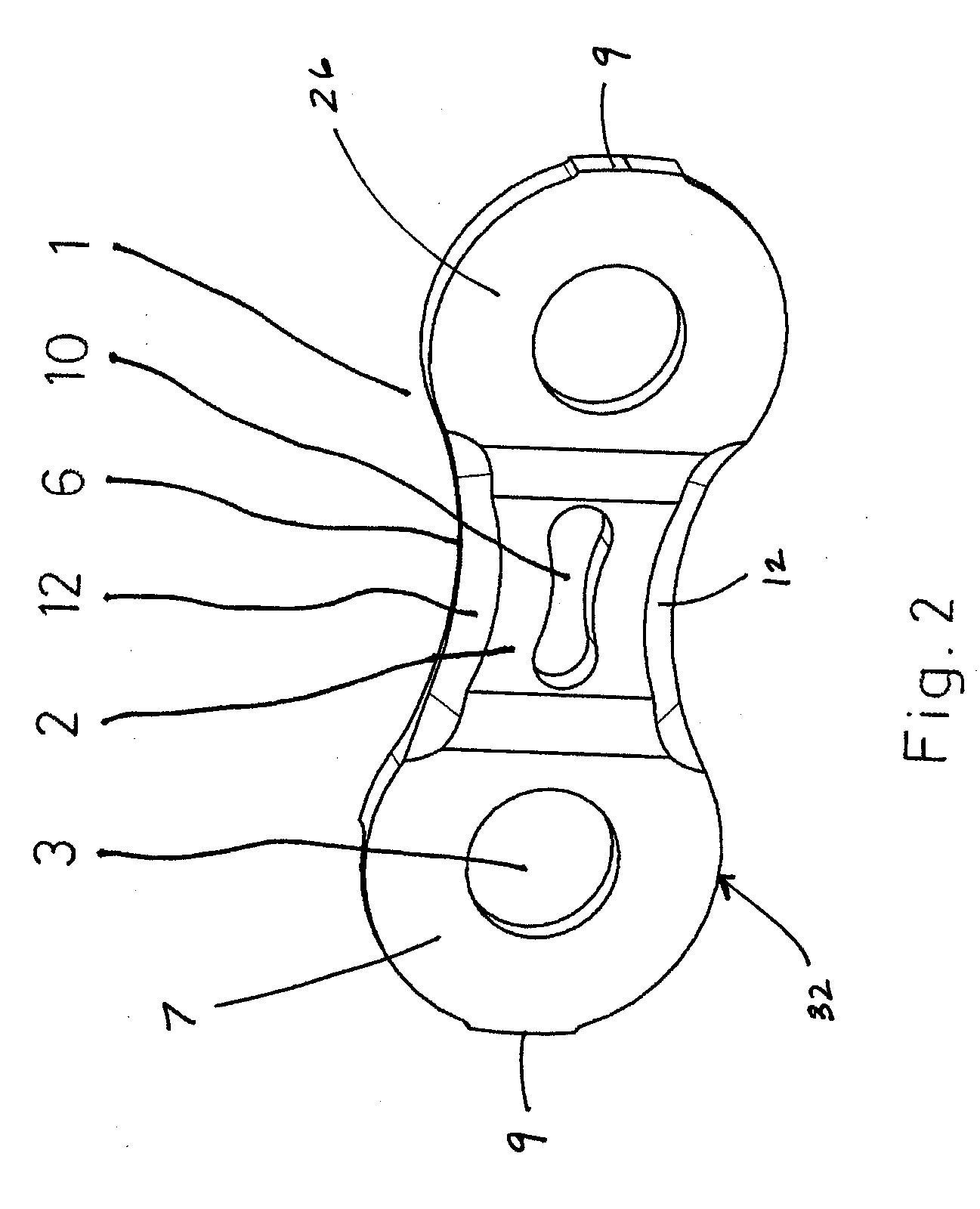
[0026] Looking to FIG. 1, the outer link plate 1 includes first and second convex sections 7, 26 and a concave section 6 extending between the first and second convex sections 7, 26. The concave section 6 has a protruding region 2 located on outer surface 33 of the outer link plate 1. The first and second convex sections 7, 26 have openings 3 for receiving the pins 18. The openings 3 have rivet head depressions 4 for receiving rivet heads 19 of the pins 18. An outer surface 5 of the protruding region 2 extends outward as far as the rivet heads 19 or projects slightly beyond them, to prevent the rivet heads 19 from scraping on the c...


PUM


Abstract

A bicycle drive chain for transferring drive force to at least one chain wheel. The chain includes a plurality of inner and outer chain links connected by pins. Chain rollers surround the pins. The inner and outer link plates have the same outer contour but have different profiles. The outer link plates have a protruding region extending from a concave section and the inner link plate includes deflection chamfers located on an outer surface. The outer link plate further includes chamfers diagonally opposed from each other located at first and second convex sections on an outer surface. The inner link plate has chamfers located on an inner surface that taper off near ends of the inner link plate.

Description

BACKGROUND OF THE INVENTION [0001] The present invention relates to bicycle drive chains and more particular to a bicycle drive chain including outer link plates having a protruding region and inner link plates, on an outer surface, having a chamfered edge. [0002] Bicycle drive chains for bicycles having a derailleur include inner and outer chain links pivotally connected to each other. These inner and outer chain links include spaces between the chain links for receiving teeth of chainwheels. The configuration of the chain links is optimized to provide a shifting operation that is quick and reliable. The shifting operations of the chain from a smaller chainwheel to a larger chainwheel and from a larger chainwheel to a smaller chainwheel are fundamentally different. During the shifting operation from the smaller to the larger chainwheel, the first tooth of the larger chainwheel engages only between an outer link plate pair. In contrast, during the shifting operation from the larger ...

Claims


Application Information

Patent Timeline
IPC IPC(8): F16G13/06
CPCF16G13/06
Inventor REITER, MARKUSSANTOS, PEDRO MIGUEL NUNES DOSPIRES, JOAO
Owner SRAM
Why Eureka
Try Eureka