Pelvis level

a technology of pelvis and pelvis, applied in the field of surgery, can solve the problems of inaccurate assessment of the inability to accurately assess the exact position or orientation of the patient,

Inactive Publication Date: 2005-09-15
BROYLES JOSEPH E
View PDF11 Cites 167 Cited by
  • Summary
  • Abstract
  • Description
  • Claims
  • Application Information

AI Technical Summary

Problems solved by technology

A common cause of such dislocation is improper positioning of the acetabular component (hip socket) in the patient's pelvic bone.
The patient may be leaning forward or backward, and there is no accurate method to assess his or her exact position or orientation.

Method used


Image

  • Pelvis level
  • Pelvis level
  • Pelvis level

Examples


Embodiment Construction

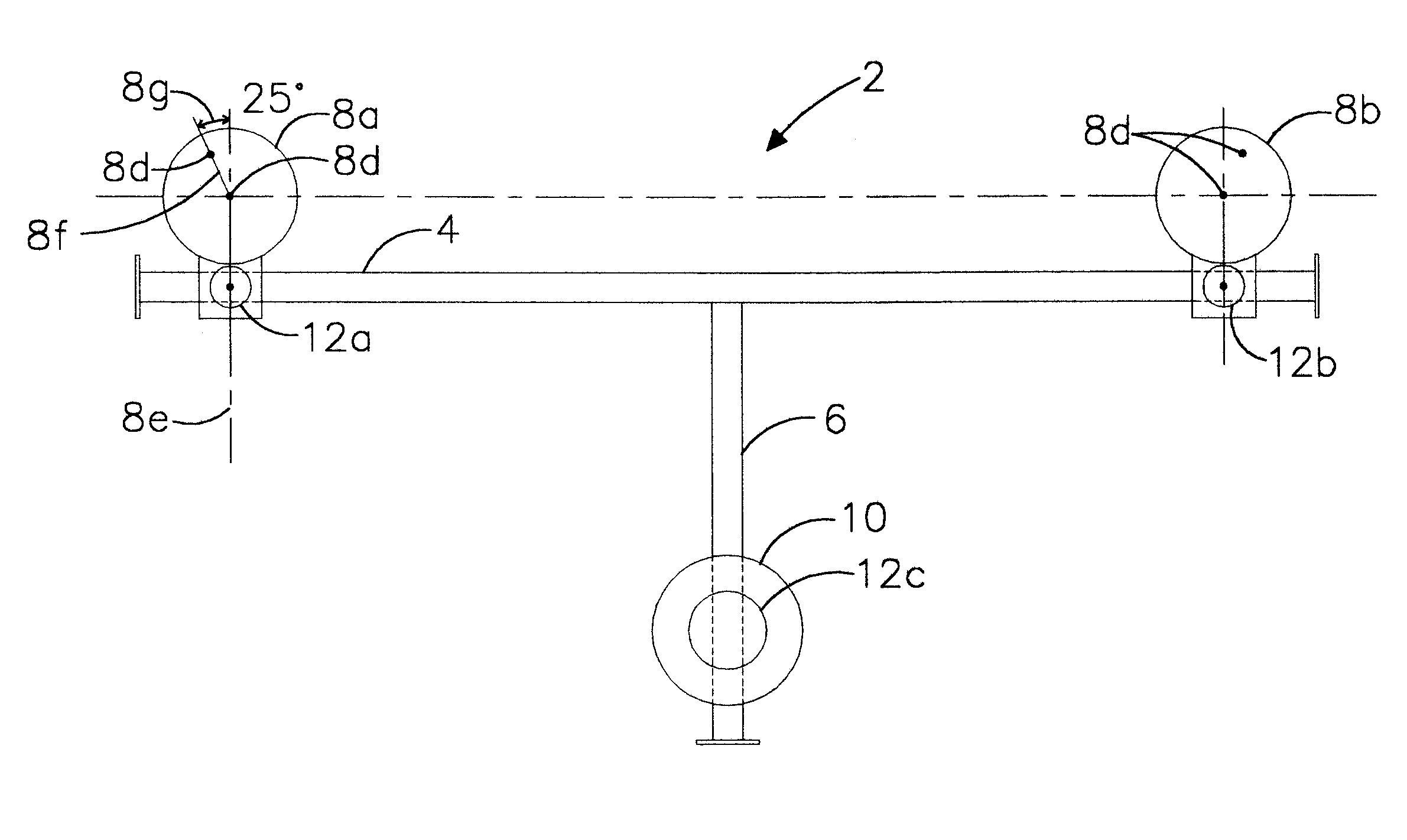
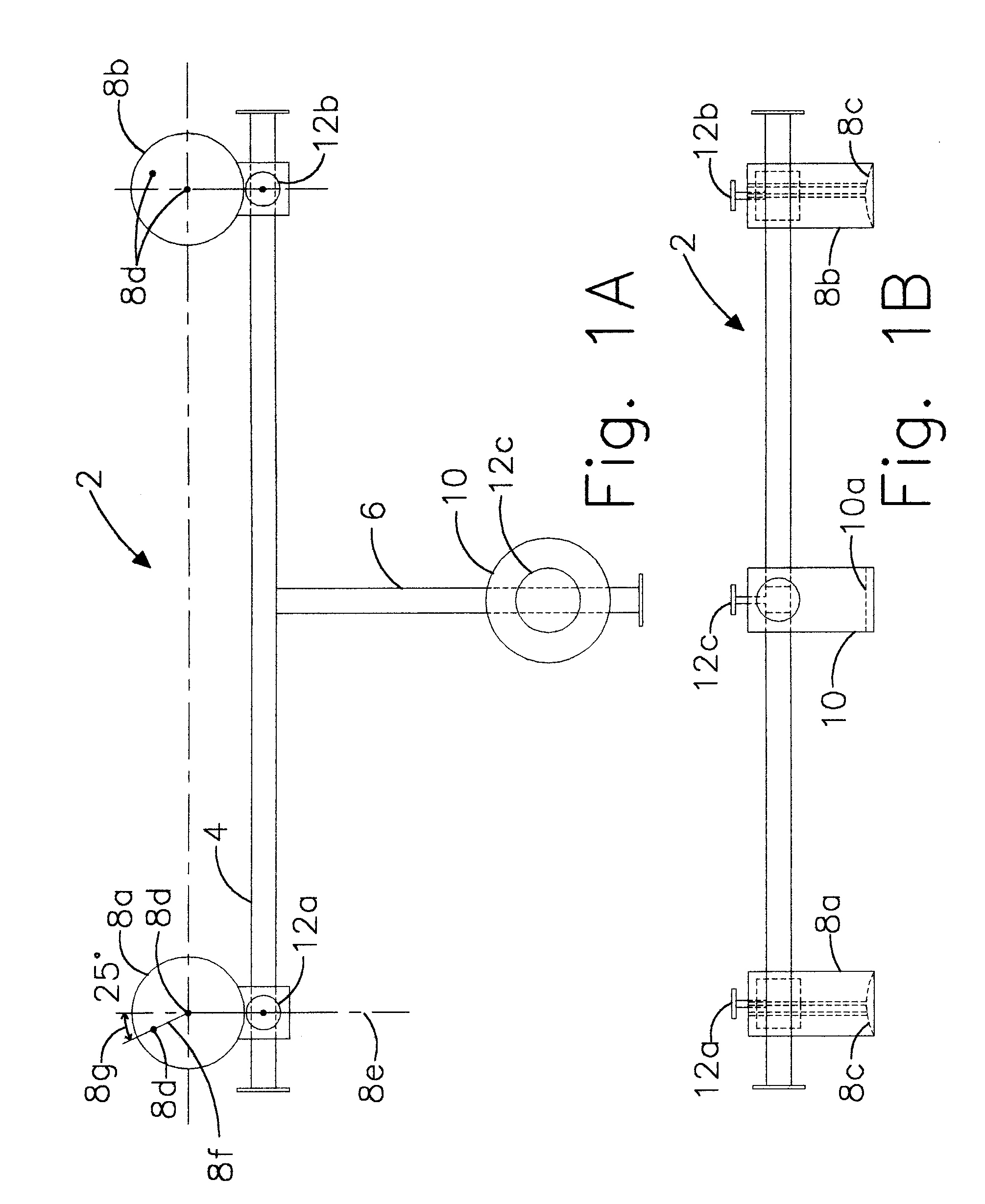
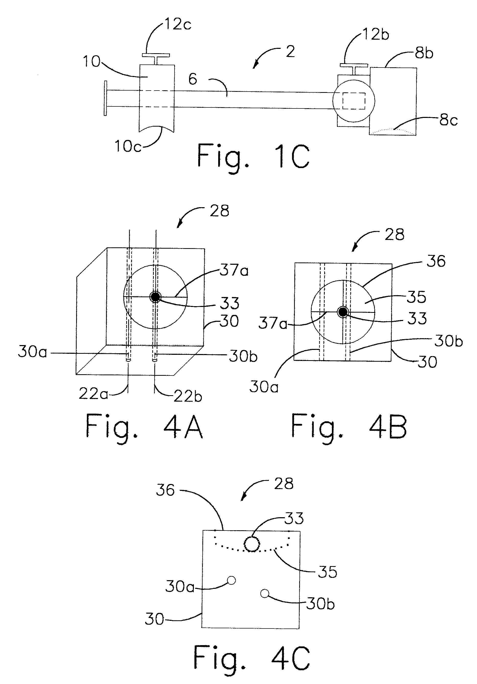
[0019] More specifically, reference is made to FIGS. 1A-1C, in which is shown a pelvis frame for hip-replacement surgery, made in accordance with the principles of the present invention, and generally designated by the numeral 2.

[0020] The pelvis frame 2 comprises a first rigid elongated member 4; a second rigid elongated member 6 mounted on the first rigid elongated member 4 in a perpendicular relationship thereto; first and second pads 8a and 8b attached to the first rigid elongated member 4 in a perpendicular configuration; a third pad 10 attached to the second rigid elongated member 6 in a perpendicular configuration; and screw-down knobs 12a, 12b, and 12c. The screw-down knobs 12a, 12b, and 12cprovide the means for varying the position of the first, second, and third pads 8a, 8b, and 10, and for fixating said position as required, for effecting orientation-determining contact of the first, second, and third pads 8a, 8b, and 10 with the pelvic bone of a patient undergoing hip-r...


PUM


Abstract

Instrumentation and method for determining the orientation of the pelvic bone during hip-replacement surgery. Instrumentation includes a pelvis frame and a pelvis level. The pelvis frame is used for performing an operation which provides preliminary information for determining the position of the pelvic bone, and includes pads which are specifically contoured for contact with the pelvic bone. The pelvis level is used in combination with the pelvis frame to determine the exact position of the patient's pelvic bone, and includes a ball level which is capable of withstanding steam sterilization.

Description

BACKGROUND OF INVENTION [0001] The present invention relates to surgery. More specifically, the invention relates to hip-replacement surgery. Such surgery is frequently performed as a treatment for arthritis of the hip. Sometimes, the hip ball can, after the operation, slip out of the hip socket. Such an occurrence is technically and medically referred to as a dislocation. A common cause of such dislocation is improper positioning of the acetabular component (hip socket) in the patient's pelvic bone. There are generally accepted angles for placement of the acetabular component that an orthopedic surgeon attempts to attain while performing the surgery. To do so, the surgeon must know or determine the orientation of the patient's pelvic bone. Herein lies the problem. The patient is covered with sterile surgical drapes, and only a small portion of the bone is visible. The patient may be leaning forward or backward, and there is no accurate method to assess his or her exact position or ...

Claims


Application Information

Patent Timeline
Patent Type & Authority Applications(United States)
IPC IPC(8): A61B17/17A61B17/58A61B19/00
CPCA61B17/1742A61B19/203A61B2019/4868A61B2019/468A61B19/46A61B2090/068A61B90/14A61B90/06A61B2090/0813
Inventor BROYLES, JOSEPH E.
Owner BROYLES JOSEPH E
Why Eureka
Try Eureka