Remote copy system

a remote copy and copying technology, applied in the field of remote copying techniques, can solve the problems of increasing the amount of data lost in disaster to the primary storage system, and achieve the effect of reducing the delay of asynchronous remote copy between the primary storage system and the secondary storage system

Inactive Publication Date: 2005-09-15
HITACHI LTD
View PDF14 Cites 31 Cited by
  • Summary
  • Abstract
  • Description
  • Claims
  • Application Information

AI Technical Summary

Benefits of technology

[0011] Consequently, the amount of delay of asynchronous remote copy between the primary storage system and the secondary storage system can be reduced as necessary, and the amount of data of the primary storage system lost in disaster can be within a configuration value.

Problems solved by technology

When the amount of delay is larger, the amount of data of the primary storage system lost in disaster is increased.

Method used


Image

  • Remote copy system
  • Remote copy system
  • Remote copy system

Examples


embodiment 1

[0025] Embodiments of the present invention will be described below using FIGS. 1 to 13.

[0026] A first embodiment of the present invention will be described using FIGS. 1 to 12.

[0027] (I) The Configuration of a Computer System

[0028] The configuration of a computer system according to the first embodiment of the present invention will be described using FIG. 1.

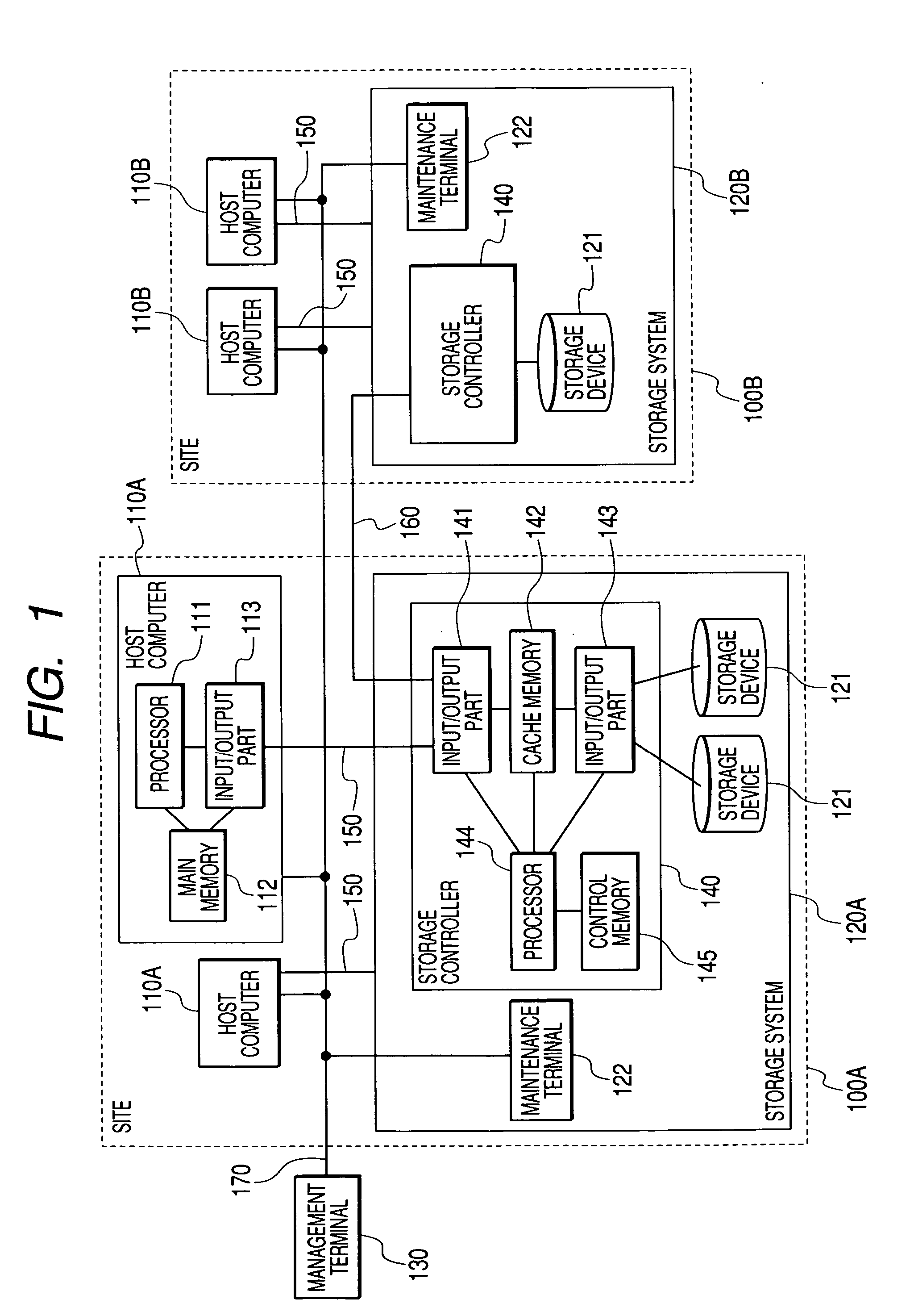
[0029]FIG. 1 is a diagram showing the hardware configuration of the computer system according to the first embodiment of the present invention.

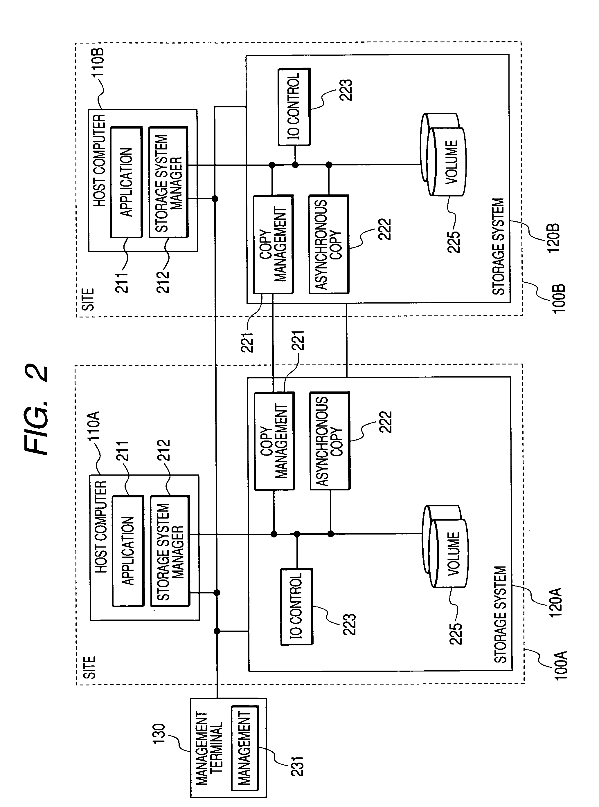
[0030]FIG. 2 is a diagram showing the functional configuration of the computer system according to the first embodiment of the present invention.

[0031] In the computer system of this embodiment, sites conjunctly perform processes and each of the sites has a host computer and s storage system.

[0032] Here, a first site is called a “primary site”, a second site is called a “secondary site”, and an example performing remote copy from the primary site to the secondary site will be desc...

embodiment 2

[0127] A second embodiment according to the present invention will be described using FIG. 13.

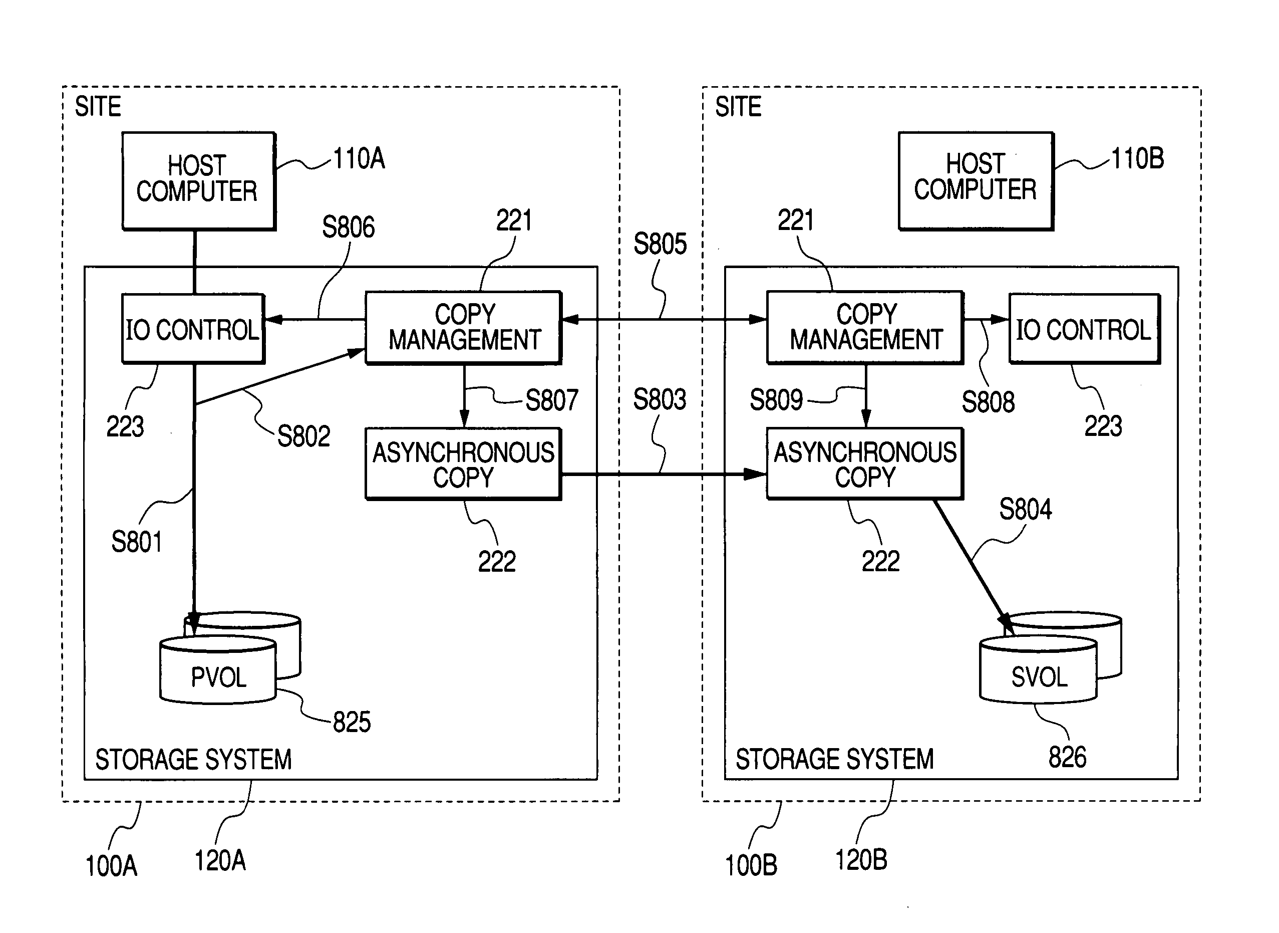
[0128]FIG. 13 is a diagram showing the operation of a process of controlling the amount of delay of asynchronous remote copy according to the second embodiment of the present invention.

[0129] A computer system of the second embodiment is different from the first embodiment in that as shown in FIG. 13, a copy management program 1321 is included in the host computer 110, not in the storage system 120, and that an IO control program 1323 is also included in the host computer 110. Each of the host computers has a communication line coupled to each other. The copy management program 1321 performs communication with the primary host computer 110A and the secondary host computer 110B. The copy management program 1321 and the IO control program of the primary host computers and the secondary host computers are communicated with each other.

[0130] In the primary site 100A, to update of data of the...


PUM


Abstract

In asynchronous remote copy, there is time difference between data update and remote copy in a primary storage system. The primary storage system loses data unreflected on a secondary storage system in disaster and cannot control the amount of data lost. The primary storage system obtains the data reflection state of remote copy between it and the secondary storage system to manage the amount of data update delay between the storage systems. When the amount of delay meets a configured start condition, a process of reducing the amount of delay is started. When the amount of delay meets a separately configured stop condition, the process of reducing the amount of delay is stopped. The configuration of whether the process of reducing the amount of delay is performed and the configuration of the conditions are performed from outside.

Description

CLAIM OF PRIORITY [0001] The present application claims priority from Japanese application No. 2004-070128, filed on Mar. 12, 2004, the content of which is hereby incorporated by reference into this application. BACKGROUND OF THE INVENTION [0002] The present invention relates to a remote copy technique duplicating data stored in a storage system to another storage system. [0003] As a technique preventing data loss in a storage system due to disaster, there is a technique duplicating data to a storage system at a remote site (remote copy). Here, the storage system includes a storage device such as a disk and a storage controller coupled to the storage device for controlling input and output of data to / from the storage device. The remote copy is a technique in which a storage system at a primary site (hereinafter, also called a primary storage system) transfers data in the source storage system to another storage system (hereinafter, also called a secondary storage system) at a remote...

Claims


Application Information

Patent Timeline
Patent Type & Authority Applications(United States)
IPC IPC(8): G06F3/06G06F12/00G06F12/16
CPCG06F11/2074G06F11/2064Y10S707/99955Y10S707/99953
Inventor KAWAMURA, SHUNJIEGUCHI, YOSHIAKIIWAMURA, TAKASHIGE
Owner HITACHI LTD
Why Eureka
Try Eureka