
Delay amount measurement method

a delay amount and measurement method technology, applied in the field of delay amount measurement method, can solve the problems of high precision, inability to compute cross-correlation functions accurately, and inability to compute delay time in amplifiers or the like, etc., and achieve the effect of high precision

Inactive Publication Date: 2007-03-27
ADVANTEST CORP
View PDF0 Cites 0 Cited by
  • Summary
  • Abstract
  • Description
  • Claims
  • Application Information

AI Technical Summary

Benefits of technology

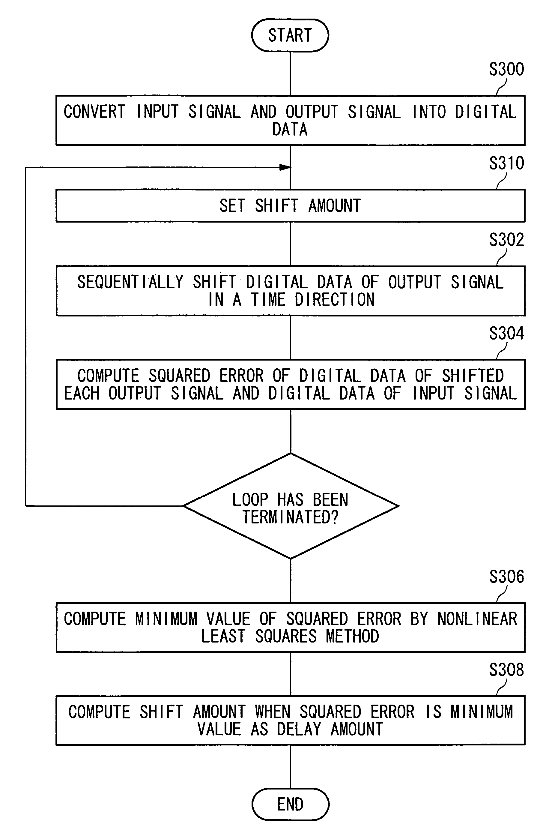
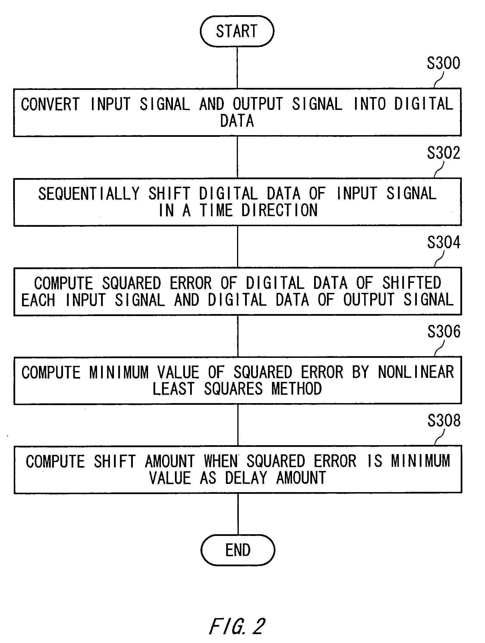
The present invention provides a method for accurately measuring delay in an electronic device. This method involves converting input and output signals to digital data, shifting them in time, and computing the squared error between them. The minimum squared error is then used as the delay amount in the device. This method is not dependent on the waveform of the output signal and can provide high precision results even in the presence of nonlinear distortion.

Problems solved by technology

However, since a cross-correlation function cannot be computed accurately when nonlinearity in characteristics of an amplifier or the like is strong, delay time in an amplifier or the like cannot be computed with high precision.
Moreover, since a phase characteristic of the cross-correlation function is discontinuous even in case of unwrapping the phase characteristic when an input waveform is a discontinuous waveform in a frequency-axis direction, e.g., like a multi-tone signal, delay time in an amplifier or the like cannot be computed with high precision.
However, there has been a problem that operation time increases extremely and thus measurement efficiency is low.
Moreover, since the operation of the phase characteristic is easy to be influenced by a noise or the like, an error may be observed significantly.

Method used


Image

  • Delay amount measurement method
  • Delay amount measurement method
  • Delay amount measurement method

Examples


Embodiment Construction

[0020]The invention will now be described based on the preferred embodiments, which do not intend to limit the scope of the present invention, but exemplify the invention. All of the features and the combinations thereof described in the embodiment are not necessarily essential to the invention.

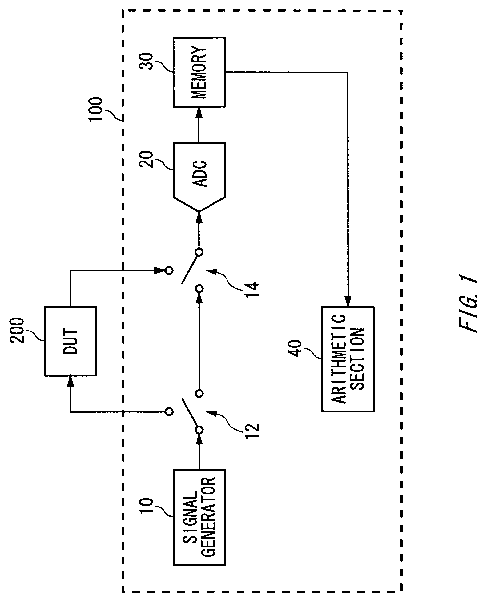
[0021]FIG. 1 is a view exemplary showing a configuration of a measuring apparatus 100 according to an embodiment of the present invention. The measuring apparatus 100 is an apparatus for measuring a nonlinear characteristic of an electronic device 200 such as an amplifier, and includes a signal generator 10, switches 12 and 14, an analog-digital converter 20 (hereinafter, referred to as an ADC 20), a memory 30, and an arithmetic section 40.

[0022]The measuring apparatus 100 stores an input signal to be input into the electronic device 200 and an output signal output from the electronic device 200 on the memory 30 in order to measure a nonlinear characteristic of the electronic device 200.

[0023...


PUM


Abstract

There is provided a delay amount measuring method of measuring a delay amount in an electronic device that outputs an output signal according to an input signal. The method includes a conversion step of converting the input signal and the output signal into digital data, a shift step of sequentially shifting the digital data of either of the input signal or the output signal in a time direction, an error computing step of computing a squared error of the digital data of the input signal and the digital data of the output signal with respect to each shift amount in the shift step, and a delay amount computing step of computing the shift amount when the squared error is a minimum value by means of a nonlinear least squares method and using the computed shift amount as the delay amount in the electronic device.

Description

CROSS REFERENCE TO THE RELATED APPLICATION[0001]The present application is a continuation application of PCT / JP2005 / 011439 filed on Jun. 22, 2005, which claims priority from a Japanese Patent application No. 2004-205178 filed on Jul. 12, 2004, the entire contents of which are incorporated herein by reference.BACKGROUND OF THE INVENTION[0002]1. Field of the Invention[0003]The present invention relates to a delay amount measuring method of measuring a delay amount in an electronic device that outputs an output signal according to an input signal.[0004]2. Description of Related Art[0005]Conventionally, when measuring a nonlinear characteristic of input and output signals of an electronic device such as an amplifier, the nonlinear characteristic is computed from an amplitude ratio and a phase difference of an input waveform and an output waveform. When such a nonlinear characteristic is computed, it is necessary to accurately match the comparison points of the input waveform and the out...

Claims


Application Information

Patent Timeline
Patent Type & Authority Patents(United States)
IPC IPC(8): G01R29/04G04F1/00
CPCG01R31/31725G01R31/3016
Inventor ASAMI, KOJI
Owner ADVANTEST CORP
Learn More