Power control of remote apparatus via network

Inactive Publication Date: 2005-09-15
FUJITSU LTD
View PDF15 Cites 85 Cited by
  • Summary
  • Abstract
  • Description
  • Claims
  • Application Information

AI Technical Summary

Benefits of technology

[0012] According to the present invention, the power-control is performed by the management apparatus when the electronic apparatus is connected to the network. In this manner, the power c

Problems solved by technology

This often results in an unnecessarily large amount of power consumption of the entire comp

Method used


Image

  • Power control of remote apparatus via network
  • Power control of remote apparatus via network
  • Power control of remote apparatus via network

Examples


Embodiment Construction

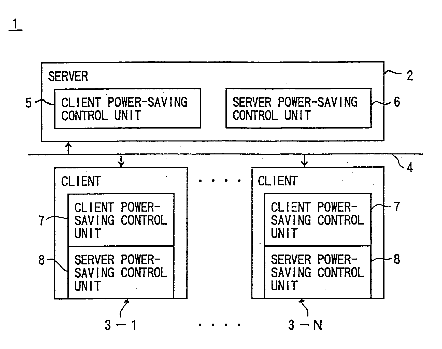
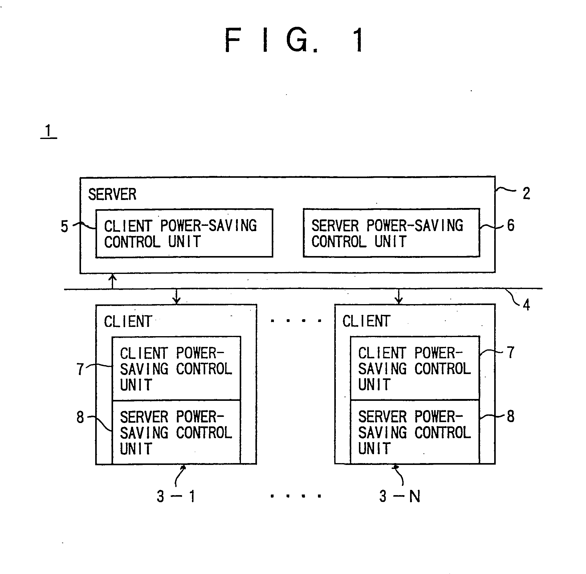
[0059]FIG. 1 is a block diagram of one embodiment of the present invention.

[0060] In an information system 1 of the present invention, a server 2 and clients 3-1 to 3-N are connected via a network 4 such as a LAN. The server 2 includes a client power-saving control unit 5 and a server power-saving control unit 6. The client power-saving control unit 5 collectively performs power-saving control for the clients 3-1 to 3-N connected to the server 2 via the network 4. The server power-saving control unit 6 performs the power-saving control for itself.

[0061] It should be understood here that a connected state of the clients 3-1 to 3-N is a state in which operating systems (OS) controlling the respective clients 3-1 to 3-N are on. On the other hand, a cut-off state of the clients 3-1 to 3-N is a state in which the operating systems (OS) controlling the clients 3-1 to 3-N are off or are physically cut off the network 4, and the network 4 cannot control the clients 3-1 to 3-N.

[0062] The ...


PUM


Abstract

A power consumption control method for collectively controlling the power consumption of electronic apparatuses connected to a network is provided. When an electronic apparatus is connected to the network, a management device performs power-saving control for the electronic apparatus. When the electronic apparatus is disconnected from the network, the electronic apparatus performs the power-saving control for itself. Thus, the power consumption of the clients connected to the network can be effectively reduced.

Description

BACKGROUND OF THE INVENTION [0001] 1. Field of the Invention [0002] The present invention generally relates to power consumption control methods, electronic apparatuses, management apparatuses, and recording-media. More particularly, the present invention relates to a power consumption control method, in which the power consumption of electronic apparatuses connected to a network is collectively controlled, and also relates to an electronic apparatus, a management apparatus, and a recording medium. Here, the electronic apparatus or the management apparatus is to be communicably “connected” to the network, with an OS (Operating System) operating in a device such as a computer which controls the operation of the electronic apparatus or the management apparatus. [0003] In recent years, as computer systems have been widely used in various fields, the ever-increasing amount of power consumption has become a problem that urgently needs a solution. In a computer system in which a large num...

Claims


Application Information

Patent Timeline
IPC IPC(8): G06F1/26G06F1/32H04L12/12
CPCG06F1/3203Y02B60/32Y02B60/34H04L12/12Y02D30/50
Inventor TOGAWA, YOSHIFUSA
Owner FUJITSU LTD
Why Eureka
Try Eureka