Post attachment device

a technology of attachment device and post, which is applied in the field of post attachment device, can solve the problem that the connecting section cannot extend through the center opening of the base, and achieve the effect of reducing the twisting of the tether

Active Publication Date: 2005-09-22
SIMPSON PERFORMANCE PRODUCTS
View PDF10 Cites 26 Cited by
  • Summary
  • Abstract
  • Description
  • Claims
  • Application Information

AI Technical Summary

Benefits of technology

[0022] In some embodiments, the degree of rotation of the catch around the post is limited to reduce the twisting of the tethers and to allow ease of detachment of the catch from the post anchor. In one (1) embodiment, the catch is only limited in rotation under normal conditions; however, the catch will rotate beyond the preset limited degree of rotation when above normal torque or excessive loads are placed on the catch or tether. In one (1) embodiment, the head of the post has an extension or nose at one end which contacts the catch when the catch rotates on the post. In another embodiment, the catch has stops which contact the extension on the head of the post and prevent full rotation of the catch on the post. In still another embodiment, the base is provided with stops and the catch contacts the stops when the catch rotates on the post to prevent the catch from rotating beyond a preset position.

Problems solved by technology

However, the size of the connector section is greater than the center opening of the base so that the connector section is not able to extend through the center opening of the base.
In one (1) embodiment, the catch is only limited in rotation under normal conditions; however, the catch will rotate beyond the preset limited degree of rotation when above normal torque or excessive loads are placed on the catch or tether.

Method used


Image

  • Post attachment device
  • Post attachment device
  • Post attachment device

Examples


fifth embodiment

[0049] In the fifth embodiment, the base 514 is provided with stops 514F adjacent the indention 514D. The stops 514F are spaced apart approximately 180° around the indention 514D. However, it is understood that the position of one or more of the stops 514F can be changed to adjust the amount of rotation of the catch 526 on the post.

[0050] The base 14, 214 and 514 in one (1) embodiment, has a frusto-conical shape. The angled sides of the base 14, 214 and 514 help to reduce damage to the base 14, 214 and 514 and harm to the user.

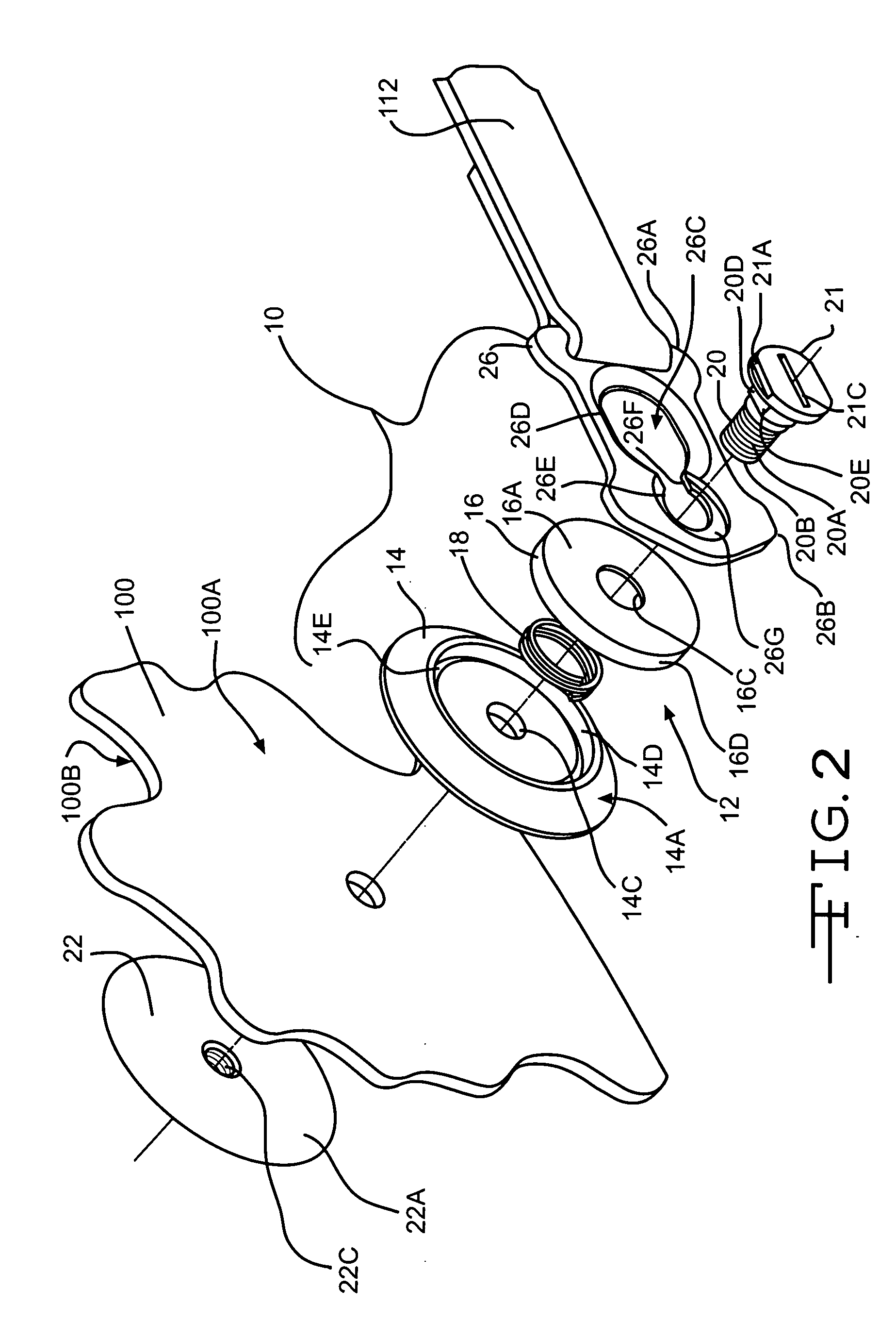
[0051] The button 16, 216 and 516 is mounted in the indention 14D, 214D and 514D of the base 14, 214 and 514 and has a shape similar to the shape of the indention 14D, 214D and 514D. In one (1) embodiment, the indention 14D, 214D and 514D is circular and the button 16, 216 and 516 has a circular cross-section. The button 16, 216 and 516 has an opening 16C and 216C which is aligned with the center opening 14C and 214C of the base 14, 214 and 514 when the butto...

second embodiment

[0061] In the second embodiment, a portion of the recess 226G in the second section 226E of the slot 226C has a second recess 226H positioned adjacent the channel 226F of the slot 226C. The sides of the catch 226 adjacent the second end 226B of the catch 226 are provided with protrusions 226I which extend beyond the sides of the catch 226 adjacent the first section 226D of the slot 226C. The protrusions 226I allow the second recess 226H around the second section 226E of the slot 226C to have a width or size greater than the width of the first section 226D. The sides of the catch 226 forming the protrusions 226I curve outward at the point where the second section 226E of the slot 226C connects to the channel 226F. The sides of the protrusions 226I angle inward toward the rounded, second end 226B of the catch 226. As the sides angle inward, the second recess 226H disappears. In one (1) embodiment, the angled sides of the protrusions 226I adjacent the rounded second end 226B of the cat...

third embodiment

[0062] In the third embodiment, the depth of the recess 326G is essentially equal to the thickness of the bottom and center portions of the head 321 of the post 320 so that the top portion of the head 321 of the post 320 with the extension 321A extends above the top surface of the catch 326.


PUM

PropertyMeasurementUnit
outer diameteraaaaaaaaaa
lengthaaaaaaaaaa
diameteraaaaaaaaaa

Abstract

A post attachment device for connecting a helmet to a head and neck support. The device includes a post anchor having a base, a button, a resilient member, a post, a retainer and a catch having a slot with a larger first section connected by a channel to a smaller second section. The button is positioned in an indention in the base with the resilient member positioned therebetween. The post extends through the button, the base and the helmet. The retainer is secured on the post adjacent the inner surface of the helmet. To secure the post attachment device, the catch is orientated over the post. The button is then pressed into the base while the catch is moved backwards to move the post into the second section of the slot.

Description

CROSS-REFERENCE TO RELATED APPLICATION(S) [0001] This application is a continuation-in-part of application Ser. No. 10 / 627,066, filed Jul. 25, 2003.STATEMENT REGARDING FEDERALLY SPONSORED RESEARCH OR DEVELOPMENT [0002] Not Applicable BACKGROUND OF THE INVENTION [0003] (1) Field of the Invention [0004] The present invention relates to a post attachment device for securing a tether between a helmet and a head and neck support device. In particular, the present invention relates to a post attachment device which uses post anchors mounted on the helmet and a catch connected to the head and neck support device to secure the helmet to the head and neck support device during use and to limit rotation of the catch on the post anchors. [0005] (2) Description of the Related Art [0006] The related art has shown several systems for connecting a head and neck support or restraint device to a helmet. One (1) such known system includes a J-clip mounted on the helmet and a D-ring connected by a tet...

Claims


Application Information

Patent Timeline
Patent Type & Authority Applications(United States)
IPC IPC(8): A41D13/05A42B1/24A42B3/04F16B21/09
CPCA41D13/0512A42B3/0473B60R22/001Y10T24/45597F16B21/09Y10T29/4984Y10T24/4599B64D10/00
Inventor STILES, MARK A.WILCOX, ALAN L.DOWNING, JAMES R.TIDWELL, SAMUEL VINCENT SR.CALDWELL, STEVE L.
Owner SIMPSON PERFORMANCE PRODUCTS
Why Eureka
Try Eureka