
Head restraint evaluator

a head restraint and evaluator technology, applied in vehicle testing, structural/machine measurement, instruments, etc., can solve problems such as the deceleration of the pendulum

Inactive Publication Date: 2005-09-22
LEAR CORP
View PDF17 Cites 13 Cited by
  • Summary
  • Abstract
  • Description
  • Claims
  • Application Information

AI Technical Summary

Benefits of technology

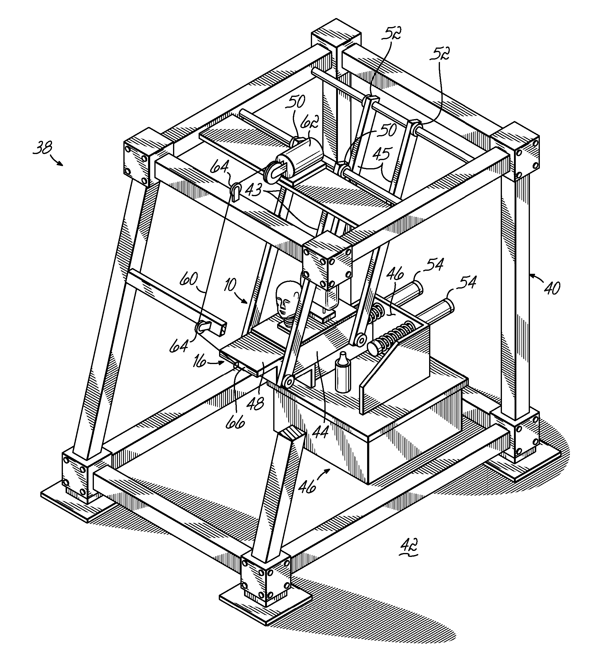
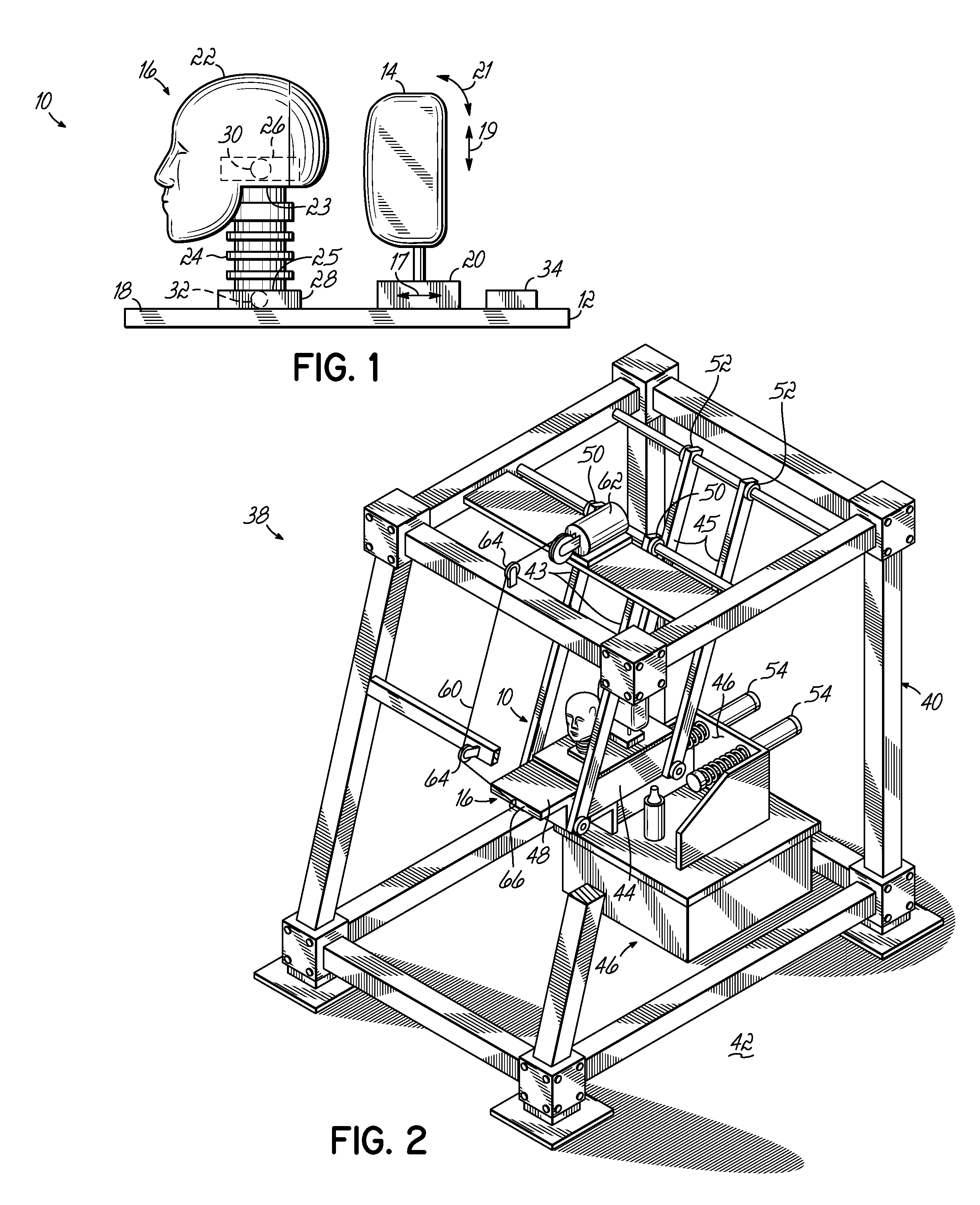
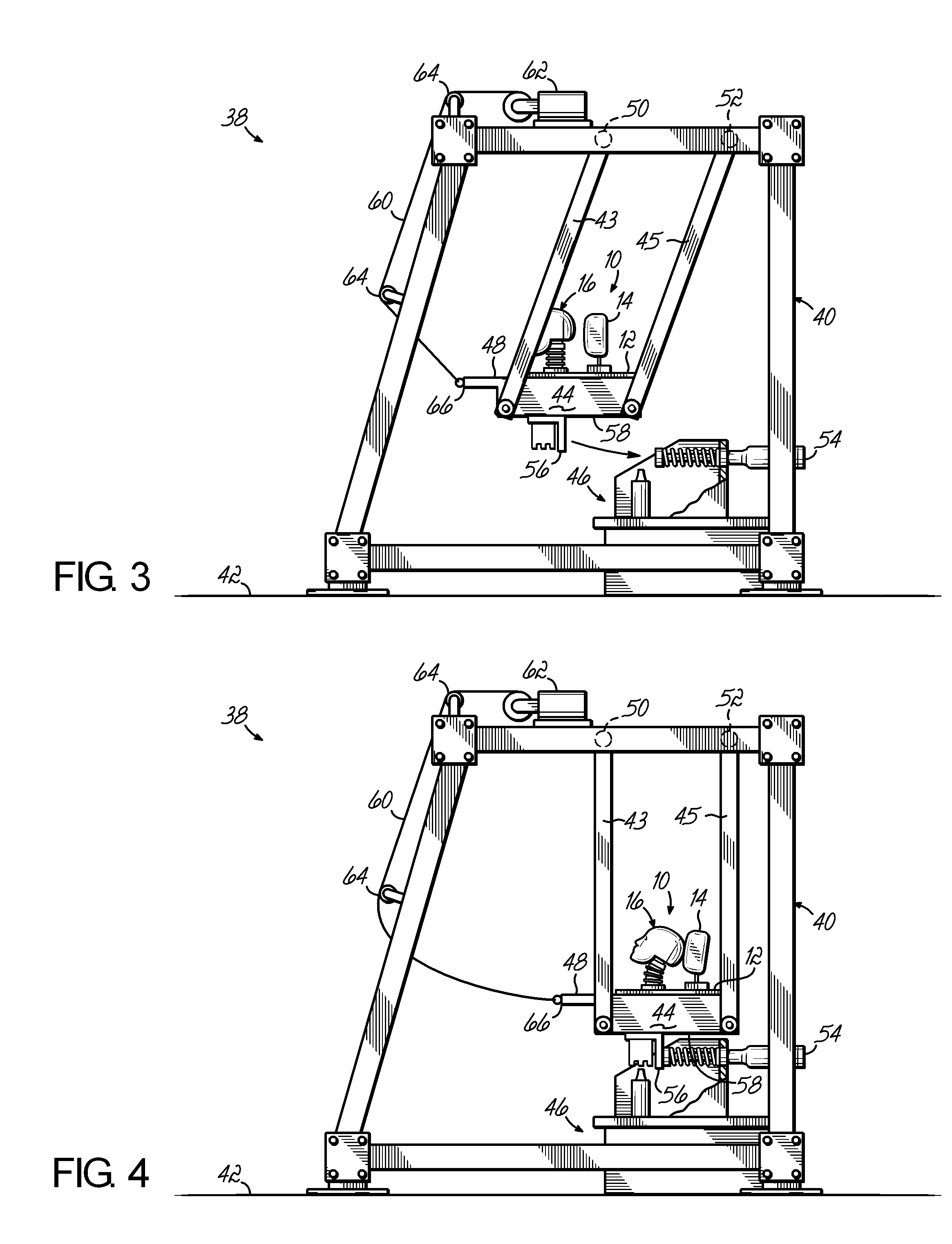
[0007] In one embodiment, the drive member comprises a pendulum having an end pivotally coupled to a frame structure and capable of swinging movement about that end and a decelerator having at least one damper configured to engage the pendulum so as to decelerate the swinging movement of the pendulum. In use, the test assembly, having the head restraint and manikin assembly mounted thereto, is mounted to the pendulum. The pendulum is then moved to a raised position and released. During the swinging movement of the pendulum, the pendulum engages at least one damper near the bottom of its swing, which causes the pendulum to decelerate. The deceleration in turn causes the head and neck portion of the manikin assembly to abruptly move in the rearward direction so that the head portion contacts the head restraint. Dynamic data, such as the imposed forces and accelerations / decelerations of the manikin assembly, may be collected and evaluated to determine the effectiveness of a particular head restraint design concept.

Problems solved by technology

During the swinging movement of the pendulum, the pendulum engages at least one damper near the bottom of its swing, which causes the pendulum to decelerate.

Method used


Image

  • Head restraint evaluator
  • Head restraint evaluator
  • Head restraint evaluator

Examples


Embodiment Construction

[0014] With reference to FIG. 1, there is shown a test assembly 10 of the present invention for evaluating head restraint design concepts. Test assembly 10 comprises a carriage 12, a head restraint 14 coupled to carriage 12 and a manikin assembly 16 also coupled to carriage 12 adjacent head restraint 14. Carriage 12 comprises a generally rectangular plate having a top surface 18. A head restraint mounting bracket 20 is coupled to carriage 12 along top surface 18 by means known but not shown. A vehicle head restraint 14 is then coupled to mounting bracket 20. Mounting bracket 20 may be adjustably positioned on carriage 12. For example, head restraint 14 may be moveable in a direction generally parallel to carriage 12 so as to move head restraint 14 toward and away from a head portion 22 of manikin assembly 16, as shown by arrow 17. As shown by arrow 19, head restraint 14 may be further moveable in a direction generally perpendicular to carriage 12 so as to adjust the height of the he...


PUM

PropertyMeasurementUnit
movementaaaaaaaaaa
forceaaaaaaaaaa
accelerationaaaaaaaaaa

Abstract

A test assembly for evaluating vehicle head restraints comprises a carriage adapted to be coupled to a drive member capable of moving the test assembly, a head restraint coupled to the carriage and a manikin assembly having a head portion and a neck portion with an upper and lower end. The head portion couples to the upper end of the neck portion and the manikin assembly couples to the carriage at the lower end of the neck assembly. The head restraint is positioned adjacent the manikin assembly so that movement of the drive member causes the head portion of the manikin assembly to contact the head restraint. The manikin assembly may further include a load cell and accelerometer for evaluating the effectiveness and performance of a particular head restraint design.

Description

FIELD OF THE INVENTION [0001] The present invention pertains generally to a vehicle component test device and more particularly to a test assembly for evaluating vehicle head restraints. BACKGROUND OF THE INVENTION [0002] The automotive industry continually strives to provide safe automobiles and so incorporate a number of safety restraint components in a vehicle that reduce the likelihood of injury in the case of a collision. One such safety restraint component is a head restraint. Such head restraints may be active or passive. It is known in the industry to provide a head restraint generally positioned on the back of the seat occupied by a driver or passenger so that in the event of a collision, such as a rear-impact collision, that tends to throw the head in the rearward direction, the head restraint will support the occupant″s head and limit head motion so as to reduce the likelihood of serious injury. [0003] Motor vehicle components must comply with minimum safety requirements ...

Claims


Application Information

Patent Timeline
Patent Type & Authority Applications(United States)
IPC IPC(8): G01M17/007G01N3/00G01N3/02
CPCG01N2203/0246G01M17/0078
Inventor YETUKURI, NAGARJUNHUMER, MLADENLOCKE, GERALD S.VEINE, ERIC
Owner LEAR CORP
Learn More