Isolation damper with proofing

a technology of damper and proofing, which is applied in the direction of ventilation systems, lighting and heating apparatus, heating types, etc., can solve the problems of sealing chamber

Inactive Publication Date: 2012-01-17
DEMSTER STANLEY J
View PDF14 Cites 8 Cited by
  • Summary
  • Abstract
  • Description
  • Claims
  • Application Information

AI Technical Summary

Benefits of technology

[0004]The damper assembly of the present invention does not rely on mechanical seals exclusively to provide the isolating function as is common in the industry. Leakage prevented by creating a high differential pressure sealing chamber in the damper assembly that prevents the flow of air from the “clean” side of the damper assembly to the “dirty” or “contaminated” side thereof. Pressurized air leaking out of the sealing chamber creates reverse flow leakage toward the dirty side which assures the clean side air is not contaminated by the dirty side air. Furthermore, the pressure in the sealing chamber is monitored with the differential pressure reported and alarmed externally if reductions in pressure indicate the sealing effect of the sealing chamber could be affected. By measuring the differential pressure from the sealing chamber to the dirty side of the damper it is possible to determine the quality and effectiveness of the damper in providing absolute isolation.

Problems solved by technology

Furthermore, the pressure in the sealing chamber is monitored with the differential pressure reported and alarmed externally if reductions in pressure indicate the sealing effect of the sealing chamber could be affected.

Method used


Image

  • Isolation damper with proofing
  • Isolation damper with proofing

Examples


Embodiment Construction

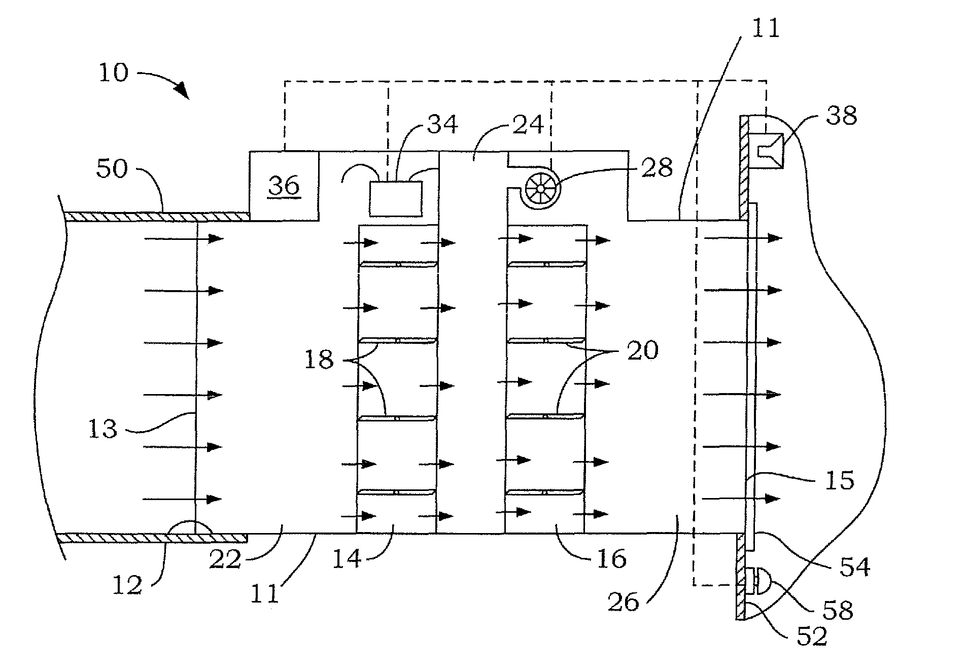
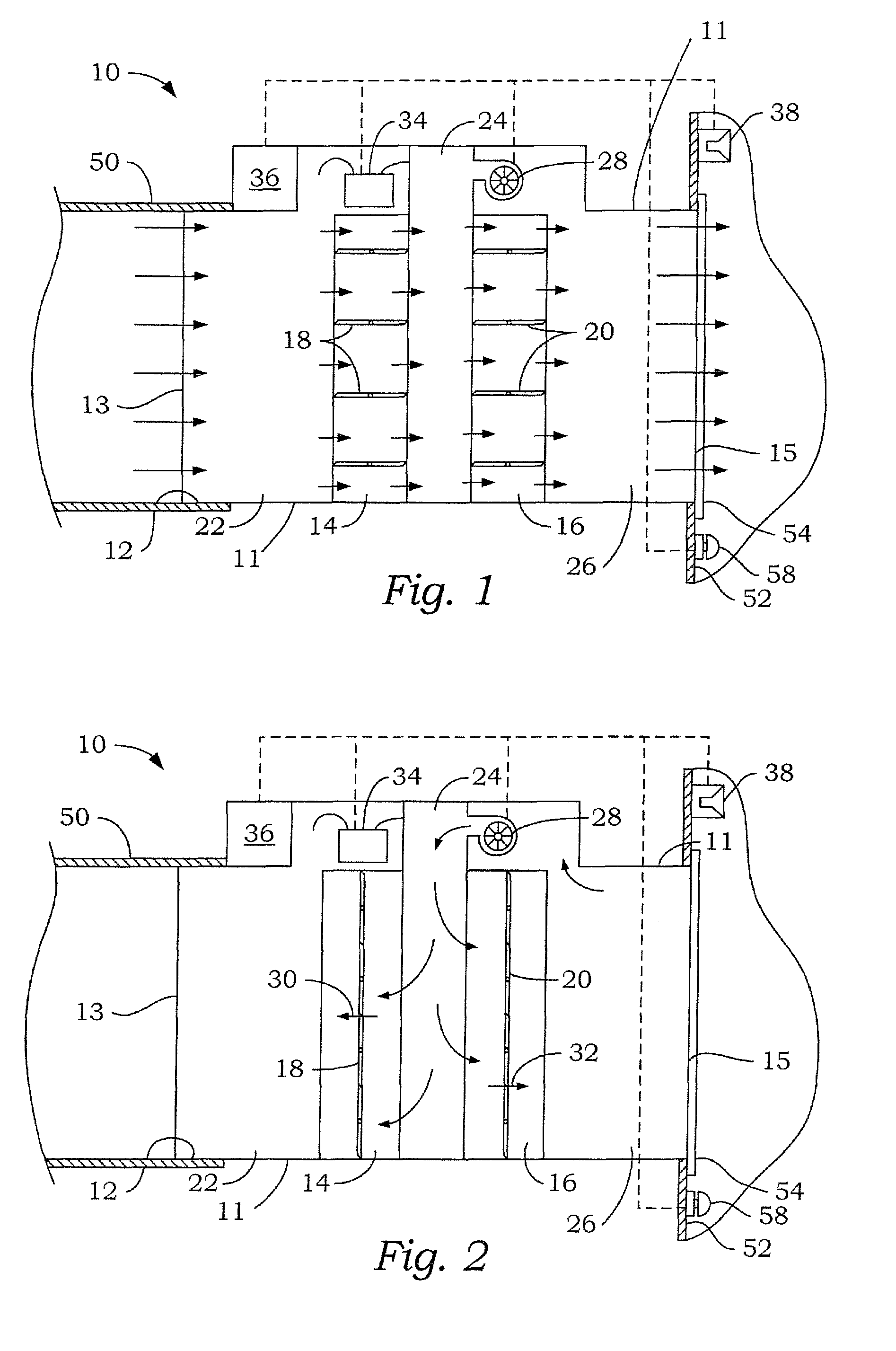
[0007]The preferred embodiment of the isolation damper assembly 10 of the present invention is shown in FIG. 1. The isolation damper assembly 10 includes a housing 11 with an interior chamber or passageway 12 with an inlet 13 and outlet 15. The housing is divided into three sections by low leakage primary and secondary dampers 14 and 16 mounted therein. The dampers 14 and 16 shown are blade-type dampers having a of plurality blades 18 and 20, respectively, moved between open and closed alignment by a damper motor, not shown. The primary and secondary dampers 14 and 16 divide the housing 11 into a first or contaminated air chamber 22, a second or high pressure sealing chamber 24, and a third or clean air chamber 26. A fan or blower 28 is mounted within the damper housing 11 to pull clean air from the clean air chamber 26 and blow it into the high pressure chamber 24.

[0008]As shown in FIG. 1, the damper 10 and primary damper 14 may be used for conventional modulation of airflow withou...


PUM


Abstract

An isolation damper for preventing the migration of air from a ventilated space includes a high differential pressure sealing chamber in the damper assembly that prevents the flow of air from the “clean” side of the damper assembly to the “dirty” side thereof. Pressurized air leaking out of the sealing chamber creates reverse flow leakage toward the dirty side which assures the clean side air is not contaminated by the dirty side air. Differential pressure between the sealing chamber and the dirty side is monitored with the differential pressure reported and alarmed externally if reductions in pressure indicate the sealing effect of the sealing chamber could be affected.

Description

CROSS-REFERENCE TO RELATED APPLICATION[0001]This application claims the benefit of a prior filed, application Ser. No. 60 / 865,125, filed on Nov. 9, 2006 entitled ISOLATION DAMPER WITH PROOFING.FIELD OF THE INVENTION[0002]The present invention relates to dampers for air delivery ducts and, more particularly, to a damper for an air duct that provides a means to isolate or seal off an air delivery duct to prevent leakage of contaminated air from an isolated containment area.BACKGROUND OF THE INVENTION[0003]Air dampers which provide low leakage are known in the art. In certain applications, a room, area or facility may require the ability to be isolated relative to the ventilation system of the building to contain chemical, biological or radiological hazards. Research laboratories, pharmaceutical production areas and chemical plants are examples where isolation is important. It is also important to provide adequate air ventilation to these facilities. If a hazardous material is spilled ...

Claims


Application Information

Patent Timeline
Patent Type & Authority Patents(United States)
IPC IPC(8): F24F13/10F24F11/00B01L1/02
CPCB01L1/02F24F13/14F24F13/15F24F13/24F24F13/1406
Inventor DEMSTER, STANLEY J.
Owner DEMSTER STANLEY J
Why Eureka
Try Eureka