Drawer for a heated food cabinet

a technology for food cabinets and drawers, which is applied in the field of drawers for heated food cabinets, can solve the problems of affecting the service life of the food cabinet, and increasing the effort and time required to clean and sanitize the food storage area, so as to facilitate full access

Inactive Publication Date: 2005-09-22
AMERICAN PERMANENT WARE CORP
View PDF10 Cites 89 Cited by
  • Summary
  • Abstract
  • Description
  • Claims
  • Application Information

AI Technical Summary

Benefits of technology

[0009] It is a further benefit of the present invention to provide a positional drawer door that facilitates...

Problems solved by technology

In the prior art devices having a permanent food storage container as part of the drawer increases the effort and time required to clean and sanitize the food storage area.
First, it is necessary to shut down the heating element for safety reasons resulting in taking the food cabinet out of service, not only for the cleaning process but also during the period of time for the heating cavity to cool and then for the period of time for the heating cavity to again attain the desired temperature.
Further, to achieve adequate cleaning the entire drawer must be removed from the food cabinet wasting time and often resulting i...

Method used


Image

  • Drawer for a heated food cabinet
  • Drawer for a heated food cabinet
  • Drawer for a heated food cabinet

Examples


Embodiment Construction

[0018] Refer now to the drawings wherein depicted elements are not necessarily shown to scale and wherein like or similar elements are designated by the same reference numeral through the several views.

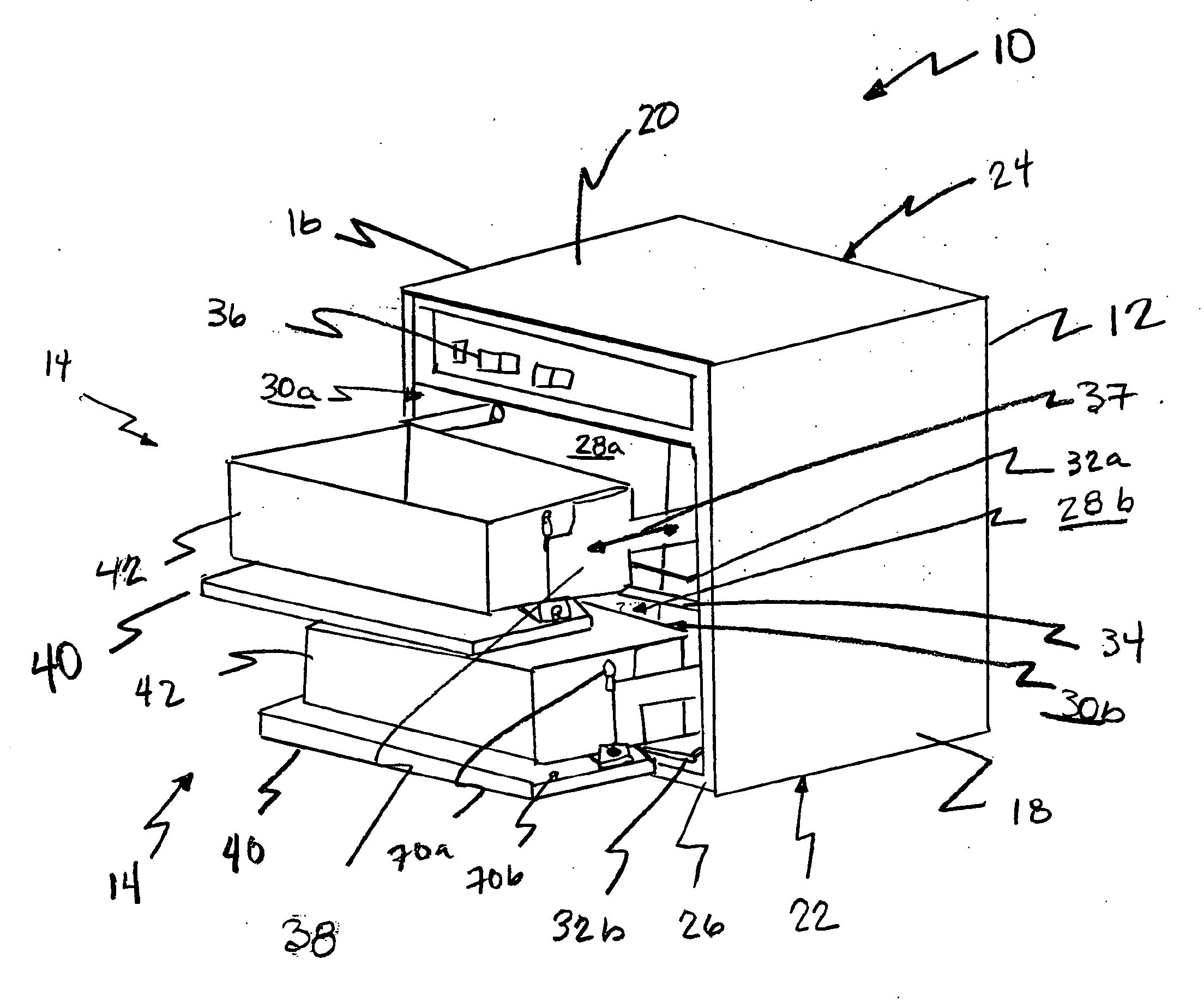
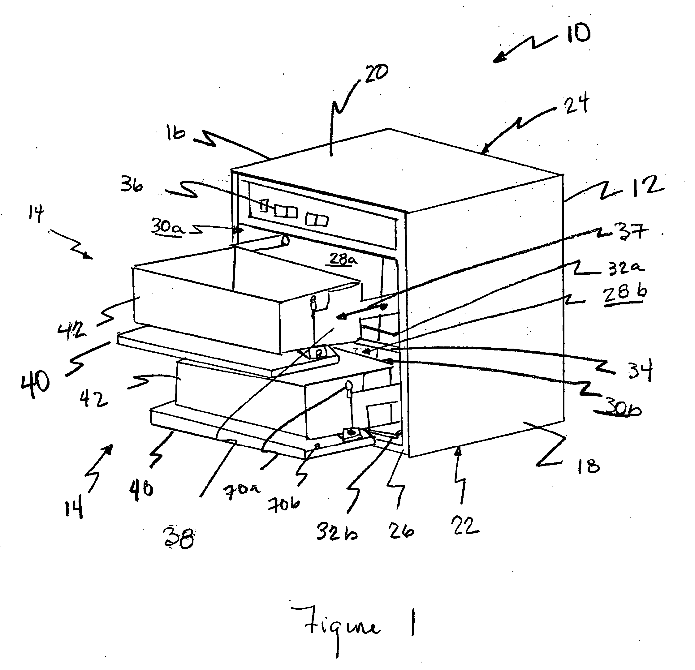
[0019]FIG. 1 is a perspective view of a positional drawer door for a food cabinet of the present invention generally designated by the numeral 10. The present invention includes a food cabinet 12 and a drawer, generally designated by the numeral 14, that is movable between a closed position in which drawer 14 is positioned within food cabinet 12 and an opened position wherein drawer 14 extends from cabinet 12.

[0020] Cabinet 12 may be a cooking or warming oven or holding oven. Cabinet 12 includes opposing side walls 16, 18, a top wall 20, a bottom wall 22, a back wall 24, and a front wall 26 forming a heated cavity 28. Cabinet 12 may be constructed of stainless steel, aluminum or other suitable material for a heating apparatus.

[0021] Access to heated cavity 28 is formed by openings ...


PUM


Abstract

The food warmer oven includes a cabinet 12 having opposing side walls 16, 18, a top wall 20, a bottom wall 22, a back wall 24, and a front wall 26 defining a heating cavity 28, the front wall 26 defining an opening 30 into the heating cavity 28; a heating source 32 disposed within the heating cavity 28; a drawer frame 38 having a pair of opposing side rails 44, 46, each of the side rails having a front end 48 and a terminal end 50, the side rails being functionally connected with the side walls 16, 18 of the cabinet in a manner such that the drawer frame 38 can be moved between an open position wherein the drawer frame 38 extends substantially exterior of the heating cavity 28 through the opening 30 and a closed position wherein the drawer frame 38 is positioned substantially within the heating cavity 28, the front end 48 of the side rails 44, 46 being positioned proximate the front wall 26 and the terminal end 50 being positioned proximate the back wall 24 when the drawer frame 38 is in the closed position; a food tray 42 removably held by the drawer frame 38; a door 40 is moveably connected to the side rails 44, 46 of the drawer frame, the door 40 moveable between an open position and a closed position; and a locking mechanism in connection between the door 40 and the side rails 44, 46 of the drawer frame 38 for selectively maintaining the door 40 in the closed position.

Description

FIELD OF THE INVENTION [0001] The present invention relates in general to a heated food cabinet and more particularly, but not limited to, a heated food cabinet that includes a moveable food drawer that has a positional drawer door. BACKGROUND [0002] Food warming devices, are often used in commercial establishments for maintaining prepared foods at a serving temperature. These cabinets are also used to reheat food products and for storage of food products that require extensive preparation time. [0003] These food warming cabinets include one or more drawers that are positional within a heated cavity. The drawers include a storage area for the food that may be either a permanent part of the drawer or a removable tray or pan. In either situation the food product must be placed in and removed from the storage area, and the storage area must be regularly sanitized. [0004] In the prior art devices having a permanent food storage container as part of the drawer increases the effort and ti...

Claims


Application Information

Patent Timeline
IPC IPC(8): F23M7/00F24C15/04F24C15/16
CPCF24C15/162
Inventor BARKER, RICHARD F. JR.KINGDON, CHARLES J.ADELMANN, CHRISTOPHER J.
Owner AMERICAN PERMANENT WARE CORP
Why Eureka
Try Eureka