Method for intensification of high-viscosity oil production and apparatus for its implementation

a technology of high-viscosity oil and intensification method, which is applied in the field of oil producing industry, can solve the problems of decreasing the efficiency of the method, insufficient efficiency, and reducing the efficiency of the device, so as to increase the efficiency of high-viscosity oil production and reduce the viscosity of oil. , the effect of increasing the permeability of the reservoir

Active Publication Date: 2005-09-22
SONOPLUS
View PDF1 Cites 11 Cited by
  • Summary
  • Abstract
  • Description
  • Claims
  • Application Information

AI Technical Summary

Benefits of technology

[0012] In the first and second objects of the invention, a technical result is achieved that lies in increasing the efficiency of production of high-viscosity oils during the development of wells by conventional methods used in the oil industry owing to a rise in the permeability of a reservoir and a reduction in the viscosity of oil and in increasing environmental safety owing to the absence of chemically active reagents (acids) and steam generators.

Problems solved by technology

The disadvantage of this method is that it does not provide for the effects on oil during its transport by oil-well tubing, thus decreasing the efficiency of the method.
The disadvantage of the method is its insufficient efficiency because it does not provide for the effect on oil during its transport by oil well tubing.
The disadvantage of this device is that it does not provide for the additional effect on the stratum and oil in the well bottom zone, decreasing the efficiency of the device.
The disadvantage of the device is that the treatment is carried out only in the oil stratum without the heating of OWT, which decreases the efficiency of the device during oil production.
The disadvantage of said Application in relation to the production of high viscosity fluids lies in the fact that it does not consider neither the heat generated in the extraction zone or the stimulation of recovered fluids during transport to the surface through the oil well tubing.

Method used


Image

  • Method for intensification of high-viscosity oil production and apparatus for its implementation
  • Method for intensification of high-viscosity oil production and apparatus for its implementation
  • Method for intensification of high-viscosity oil production and apparatus for its implementation

Examples


Embodiment Construction

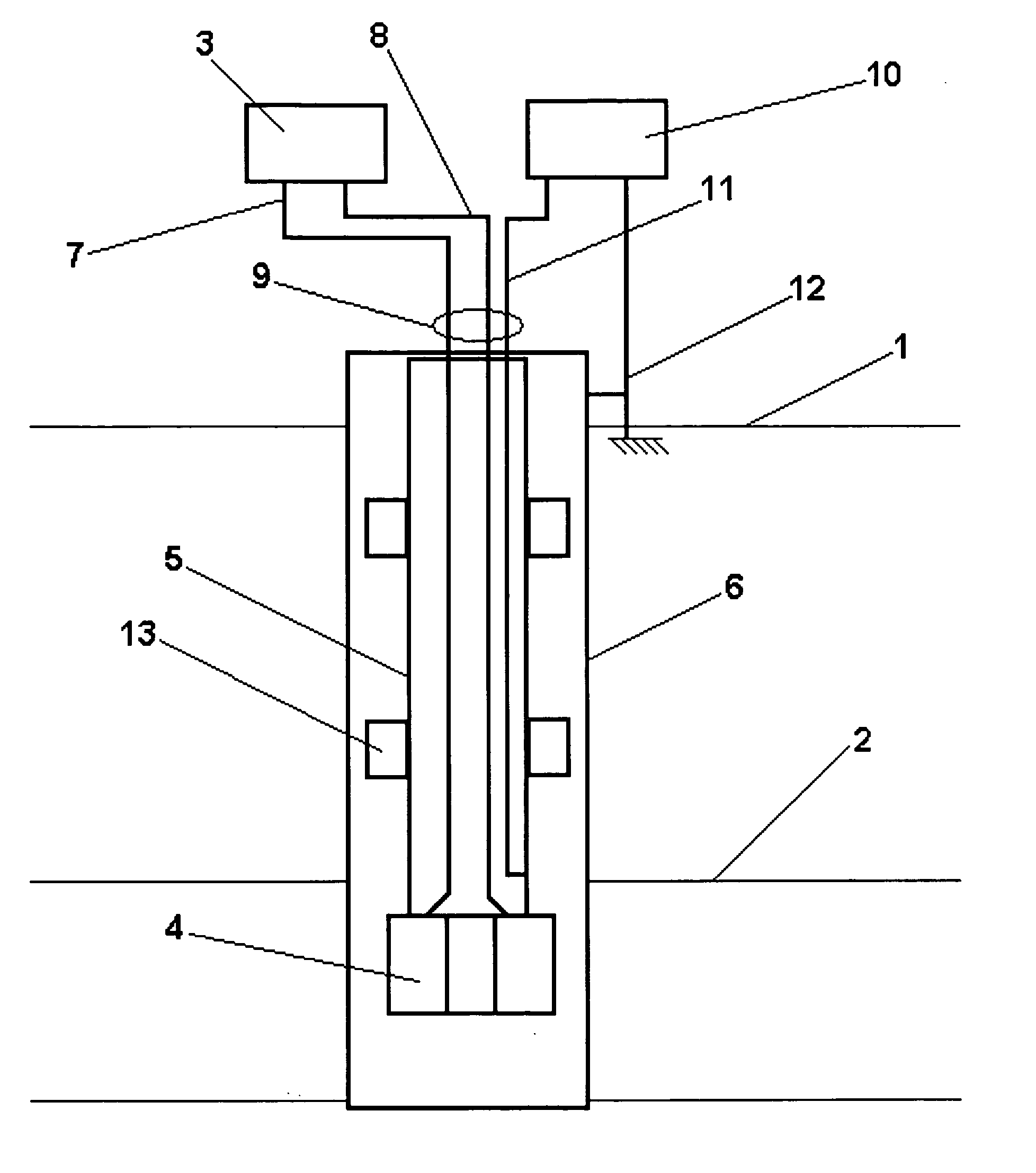
[0025] The invention is illustrated in FIGS. 1-4, by a schematic drawing in which an apparatus for the implementation of the method for intensification of production of high-viscosity oils with different cases for the connection of the heating line of the OWT beating unit by high-frequency currents is presented.

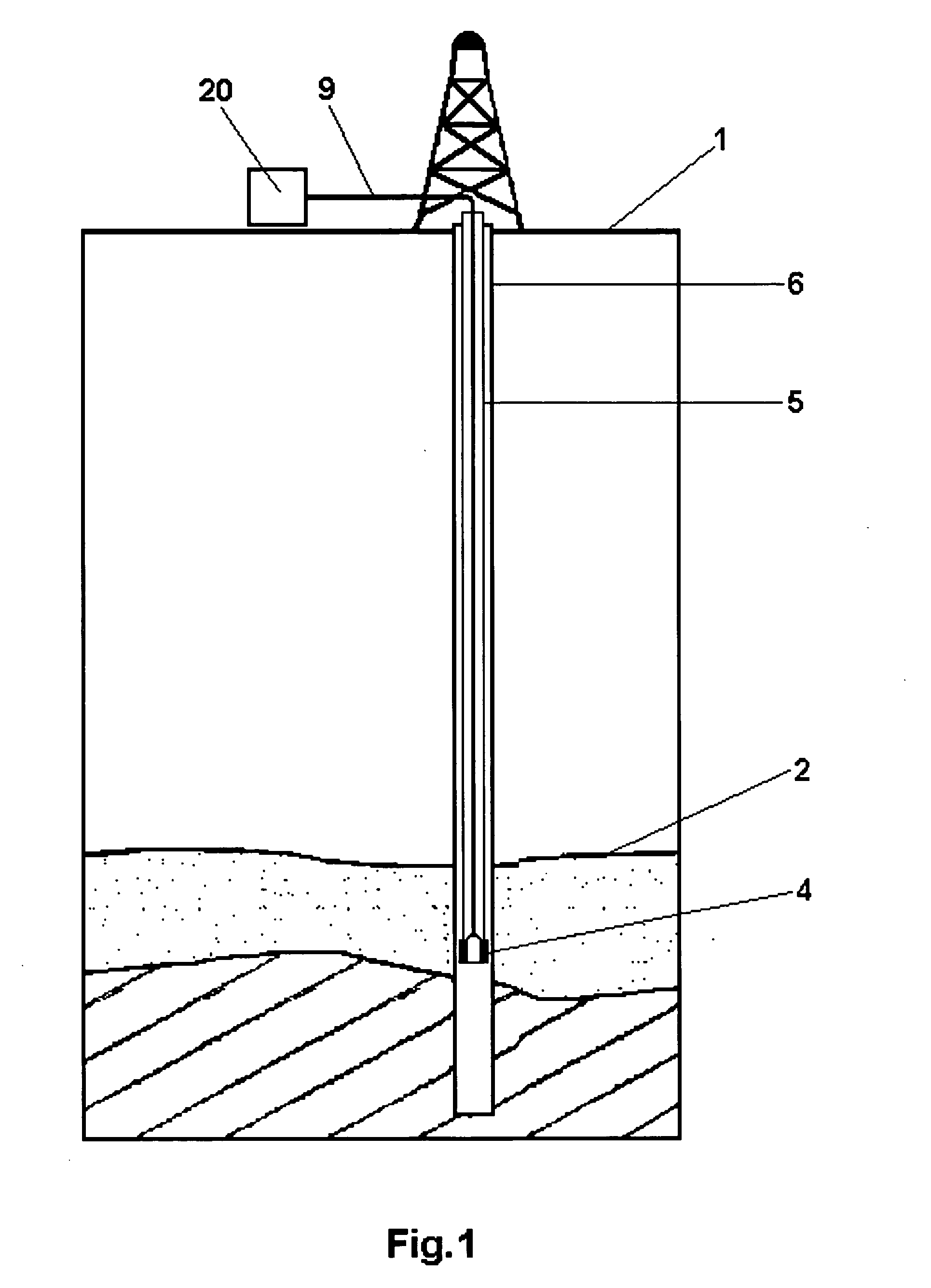
[0026]FIG. 1 shows the general structure of the oil well and the a surface device 20 at daylight level 1 (which contains the surface ultrasonic generator 3 and the daylight surface high frequency generator 10) and the ultrasonic magnetostrictive radiator 4 at the end of the oil well tubing 5, connected by the three-cord electrical cable 9.

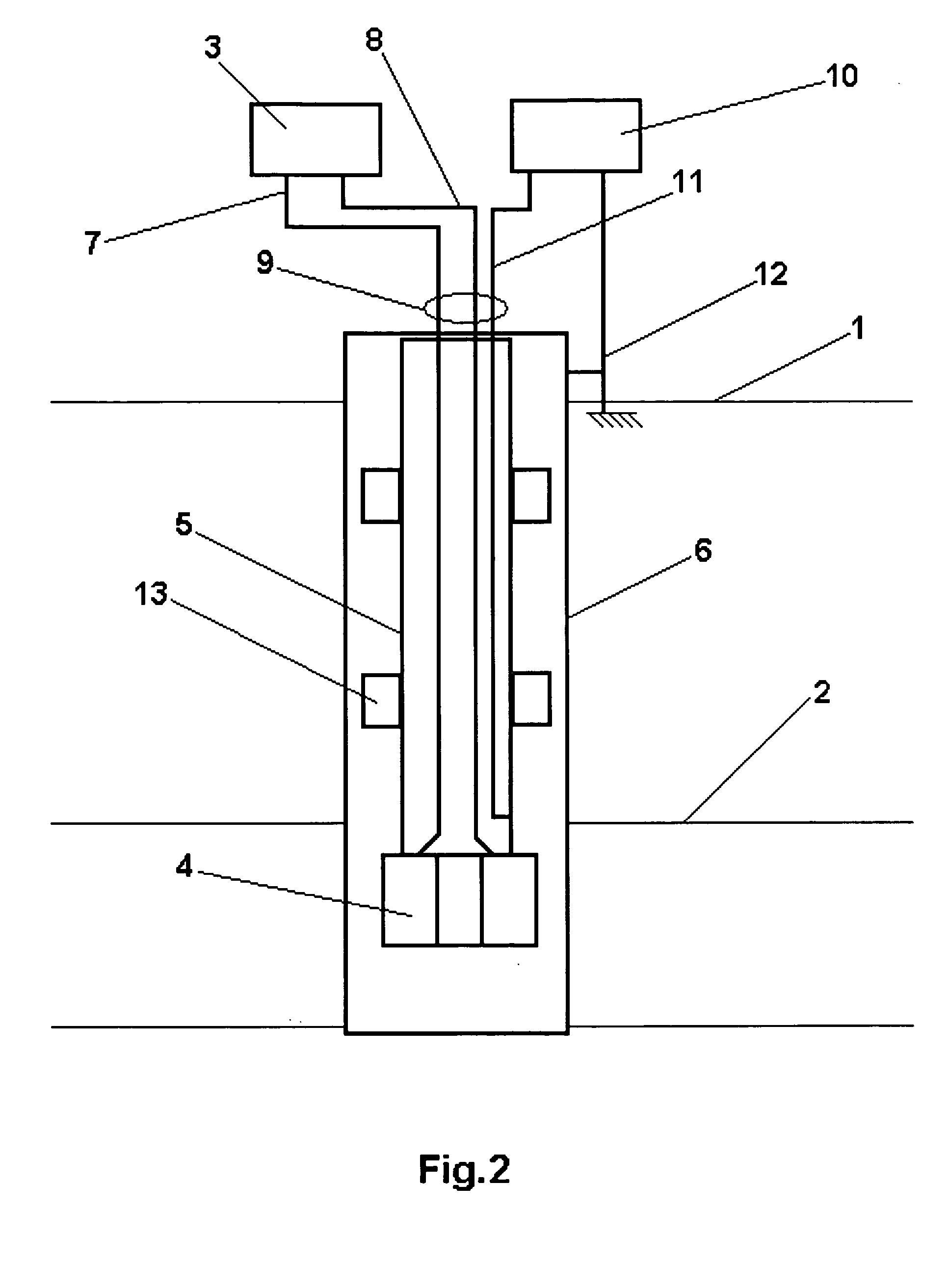
[0027] The following is shown in FIG. 2: the daylight level 1, stratum-reservoir 2, the unit of ultrasonic excitation of the well bottom zone which includes the surface ultrasonic generator 3 and at least one ultrasonic magnetostrictive radiator 4 placed at the end of OWT 5.

[0028] The ultrasonic magnetostrictive radiator 4 is made in the ...


PUM


Abstract

The invention applies to the oil-producing industry and is intended for the intensification of processes increasing the yield of. oil wells developed by conventional methods during production of high viscosity oils. Both objects of said invention have as a technical result an increase in the permeability of a reservoir and a reduction in the viscosity of oil, added to an increase in environmental safety by avoiding use of chemical reagents and steam generators. First object of said invention applies a high power ultrasonic field in the well bottom 10 zone that reduces viscosity of oil, also heating said zone. Second object of said invention comprises a surface ultrasonic generator and at least one ultrasonic magnetostrictive radiator placed at end of oil well tubing, using high frequency currents that warm said tubing maintaining viscosity of oil during transport to the surface.

Description

FIELD OF APPLICATION [0001] The invention applies to the oil-producing industry and is intended for the intensification of the processes of increasing the yield of oil wells used for the production of high-viscosity oils. BACKGROUND OF THE INVENTION [0002] At present, a fairly large number of methods and apparatuses are known that allow enhancement of production processes for high-viscosity oils. In most cases, these techniques employ physicochemical methods of influence on a stratum (well bottom zone) and on transport systems that transport oil from the stratum to the surface. In particular, it is proposed to add different reagents into a well and to influence strata by elastic vibrations of different frequency, shock waves, magnetic and electric fields or combinations thereof. In some cases, the use of devices that include sources of elastic vibrations and systems of induction beating are provided. [0003] A method for intensification of oil production by the excitation of elastic ...

Claims


Application Information

Patent Timeline
Patent Type & Authority Applications(United States)
IPC IPC(8): E21B28/00E21B36/04E21B43/00E21B43/24
CPCE21B28/00E21B43/24E21B43/003E21B36/04E21B43/00
Inventor ABRAMOV, OLEGABRAMOV, VLADIMIRPECHKOV, ANDREYZOLEZZI GARRETON, ALFREDOPAREDES-ROJAS, LUIS
Owner SONOPLUS
Why Eureka
Try Eureka