
Fluid-filled vibration damping device

a technology of vibration damping and flue gas, which is applied in the direction of shock absorbers, jet propulsion mountings, machine supports, etc., can solve the problems of relativly large vibration transmission or impulsive noise, vibration and noise may be created, and achieve excellent damping effect, simple construction, and avoidance of resultant vibration and noise. advantageous

Inactive Publication Date: 2005-09-22
SUMITOMO RIKO CO LTD
View PDF8 Cites 34 Cited by
  • Summary
  • Abstract
  • Description
  • Claims
  • Application Information

AI Technical Summary

Benefits of technology

[0011] It is therefore one object of the present invention to provide a fluid-filled vibration damping device of improved structure which is capable of ensuring excellent vibration damping device on the basis of flow action of the non-compressible fluid sealed therein, while eliminating or minimizing creation of vibration or noise upon input of impulsively large vibration or load thereto, and which is readily cheap to manufacture with a reduced number of components and a simple construction.

Problems solved by technology

Meanwhile, these fluid-filled vibration damping devices having such a conventional structure, may suffer from relatively large vibration transmission or impulsive noises created when an impulsive substantial vibrational load is applied between the first mounting member and the second mounting member.
For instance, when the conventional device is used as an automobile engine mount, such vibration and noises may be created upon engine cranking or abrupt acceleration of the vehicle.

Method used


Image

  • Fluid-filled vibration damping device
  • Fluid-filled vibration damping device
  • Fluid-filled vibration damping device

Examples


Embodiment Construction

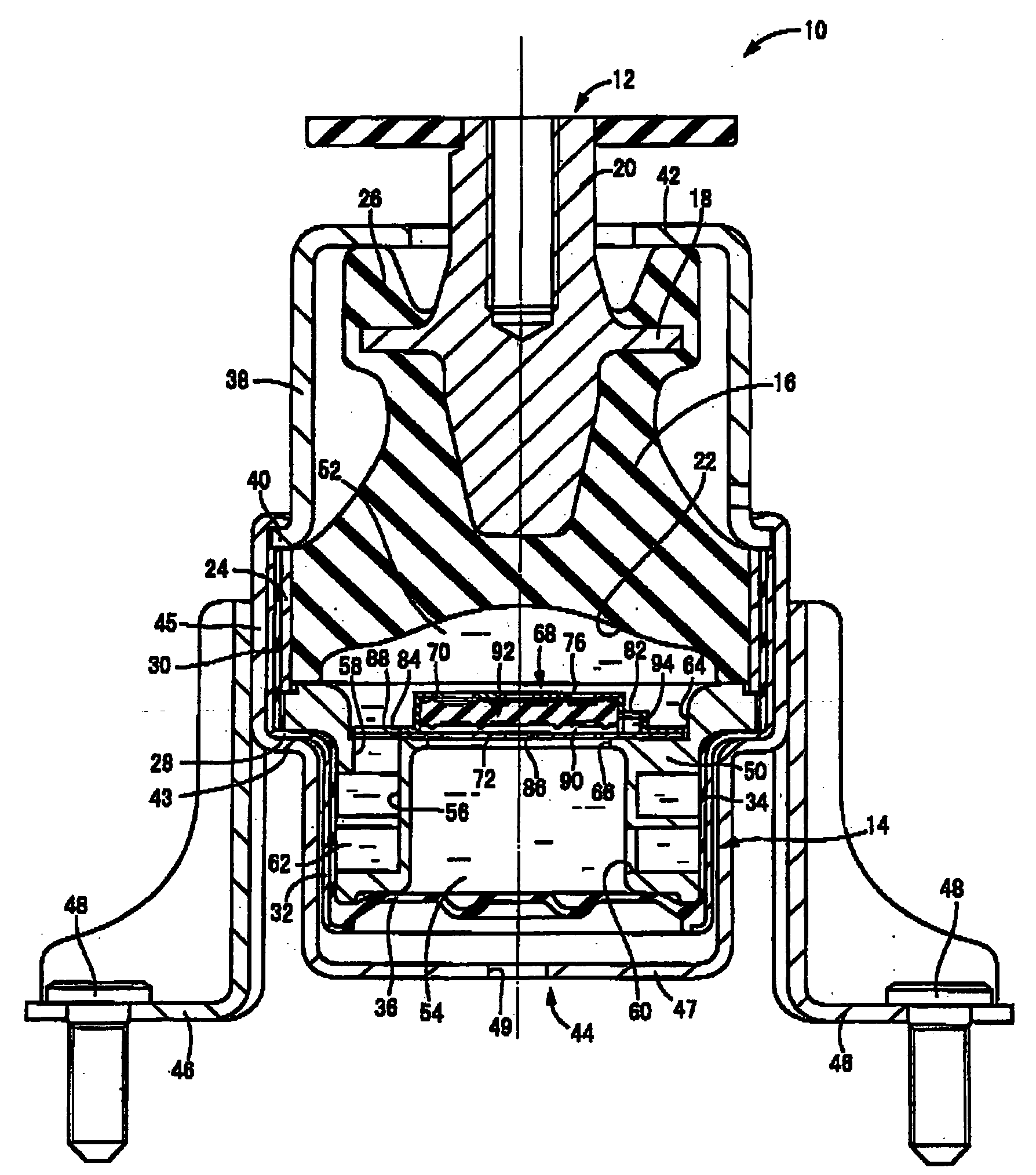
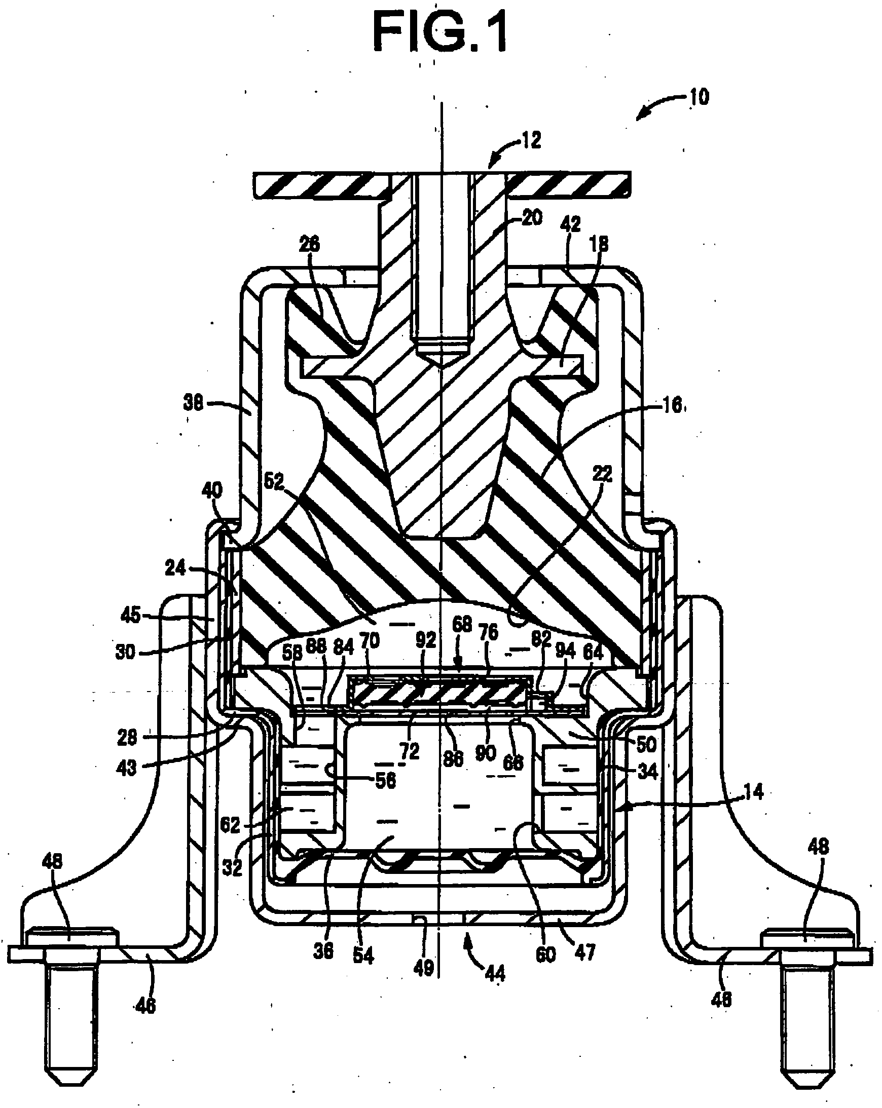
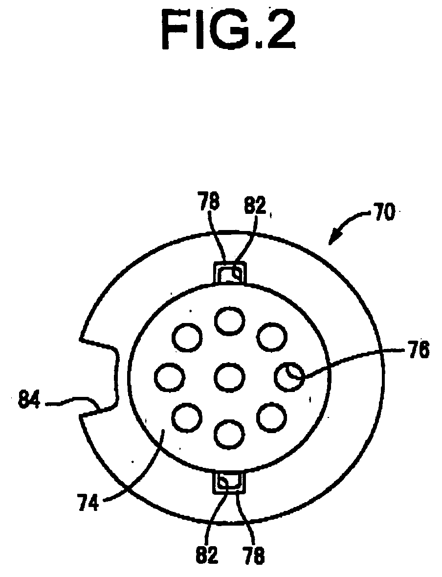
[0042] Referring first to FIG. 1, shown is an engine mount 10 for an automotive vehicle, having construction according to a first embodiment of a fluid-filled vibration damping device of the present invention. The engine mount 10 includes a first mounting member 12 of metal, a second mounting member 14 of metal, and an rubber elastic body 16 by which are elastically connected the first mounting member 12 and the second mounting member 14 disposed spaced away from each other. The engine mount 10 is installed on the vehicle such that the first mounting member 12 is fixed to the power unit side of the vehicle, while the second mounting member 14 is fixed to the body side of the vehicle, whereby the engine mount 10 fixedly supports the power unit on the body of the vehicle in a vibration damping fashion, like conventional engine mounts. With the engine mount 10 installed on the vehicle as described above, the rubber elastic body 16 undergoes elastic deformation due to a static load or w...


PUM


Abstract

A fluid-filled vibration damping device including: an elastic body connecting a first and a second mounting member, defining a pressure receiving chamber undergoing pressure fluctuation during input of vibration; an equilibrium chamber defined by a flexible layer for permitting its volume change; an orifice passage connecting the pressure receiving chamber and equilibrium chamber; a movable member; and a short passage for connecting two chambers with a length smaller than that of the orifice passage. When pressure in the pressure-receiving chamber increases, the movable member is displaced or deformed toward to close the equilibrium-chamber-side opening of the short passage to have the short passage substantially closed, while when pressure in the pressure-receiving chamber decreases, the movable member is displaced or deformed to have the short passage operative.

Description

INCORPORATED BY REFERENCE [0001] The disclosure of Japanese Patent Application No. 2004-083641 filed on Mar. 22, 2004 including the specification, drawings and abstract is incorporated herein by reference in its entirety. BACKGROUND OF THE INVENTION [0002] 1. Field of the Invention [0003] The present invention relates generally to fluid-filled vibration damping devices suitably used as an automobile engine mount, body mount, differential mount, and the like, and more particularly to a fluid-filled vibration damping device capable of exhibiting vibration damping effect based on vibration damping characteristics exhibited by flow action of the fluid sealed therein. [0004] 2. Description of the Related Art [0005] As one type of vibration damping couplings or mounts, there is known a fluid-filled vibration damping device that is capable of exhibiting vibration damping effect on the basis of resonance or flow action of the non-compressible fluid sealed therein. [0006] In order to meet a ...

Claims


Application Information

Patent Timeline
IPC IPC(8): B60K5/12F16F5/00F16F13/00F16F13/06F16F13/10F16F13/18F16M7/00
CPCF16F13/106
Inventor MAENO, HAJIMEMURAMATSU, ATSUSHI
Owner SUMITOMO RIKO CO LTD
Learn More