
Interior illumination lamp

a technology for interior lighting and lamps, applied in the direction of lighting and heating apparatus, lighting support devices, coupling device connections, etc., can solve the problems of trouble, unfavorable economics, etc., and achieve the effect of reducing cost and easy attachmen

Active Publication Date: 2005-09-22
YAZAKI CORP
View PDF2 Cites 16 Cited by
  • Summary
  • Abstract
  • Description
  • Claims
  • Application Information

AI Technical Summary

Benefits of technology

[0011] In the interior illumination lamp configured in such a manner, the design part is attached to the aperture arranged in an interior material of an automobile, and the functional part, provided with a light source, is attached to the rear side of the interior material by being supported by the design part. The switching unit feeding and cutting an electric power to the light source is attached to the functional main body as a separately configured unit, and thus a plurality of switching units each differing in the on / off mechanism can be selectively attached. For that reason, even if the switching unit is changed, the functional unit can be used in common and has a general-purpose nature, thus leading to cost reduction.
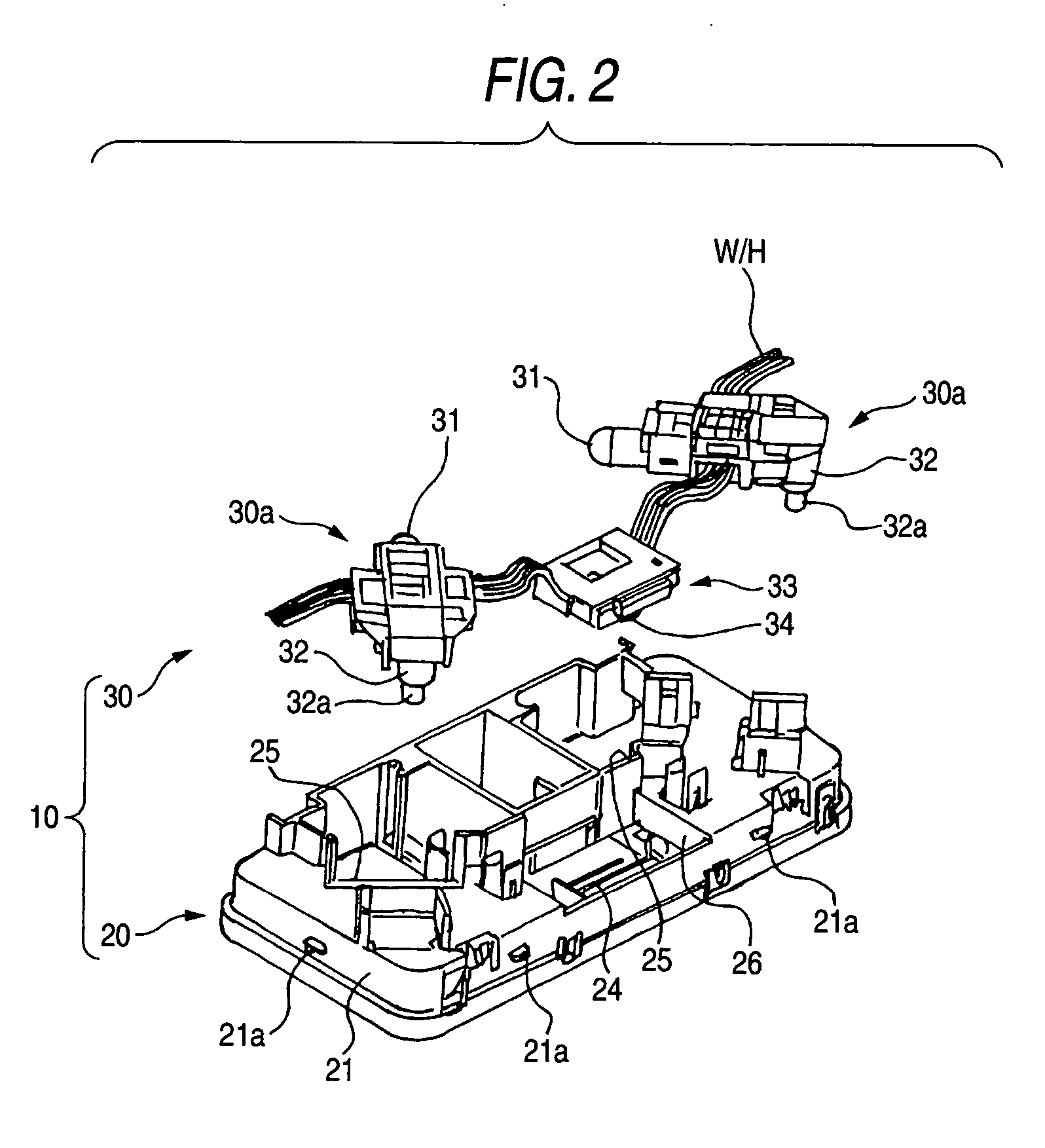
[0013] In an interior illumination lamp thus configured, at the attachment operation of the switching unit to the accommodation unit of the functional main body, the switching unit is positioned at a predetermined place in the accommodation unit according to the guiding means and fixed there. In addition, since the switching unit is electrically connected to the main body by means of the connecting means by accommodating the switching unit in the accommodation unit of the functional main body, the switching unit can be easily attached to the functional main body.
[0014] According to the invention, the problem accompanied by a conventional room illuminating light, in which a switching unit and a functional part are integrally configured, that for a different switching unit the functional part has to be newly produced in conformity with the shape of the switch can be solved, since the functional unit can be used in common for different switching units, thus leading to cost reduction.

Problems solved by technology

For that reason, in the case where a switch of a different shape (for example, push-lock type, sliding switching type, alternate-lock type, etc.) is adopted or exchanged, the entire function-concentrated unit 101 had to be newly produced in conformity with the shape of the switch and install the switch therein, which was not only troublesome, but also unfavorably uneconomical.

Method used


Image

  • Interior illumination lamp
  • Interior illumination lamp
  • Interior illumination lamp

Examples


Embodiment Construction

[0025] In the following, some embodiments associated with the invention are described in detail based on drawings.

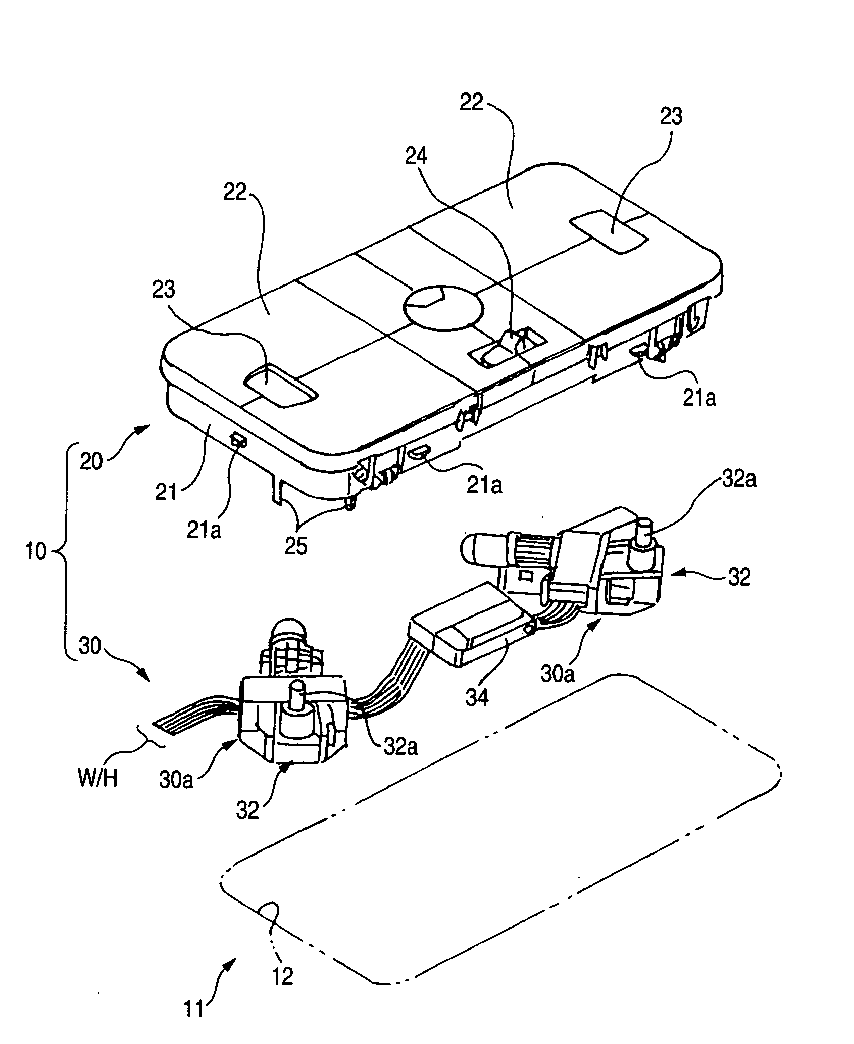
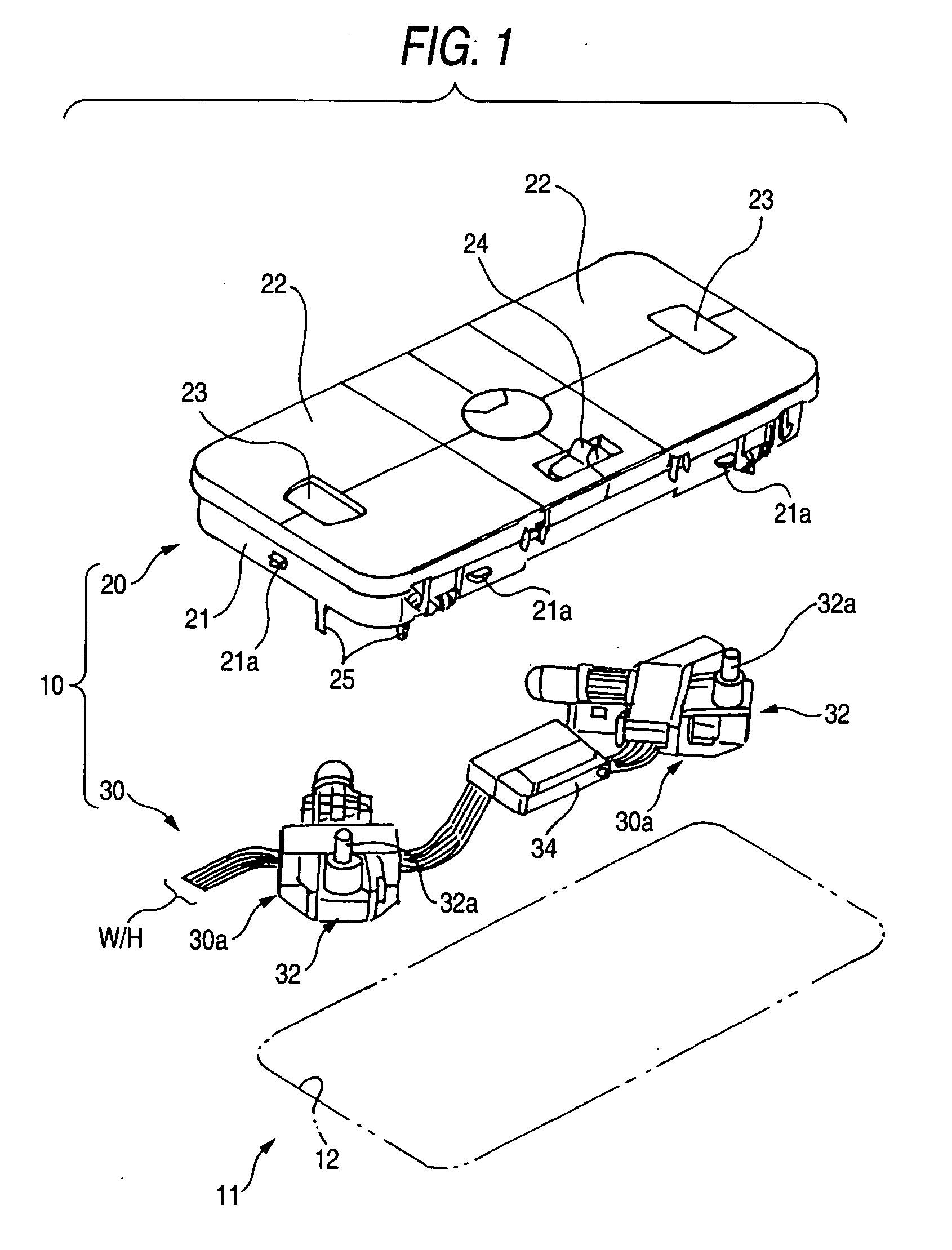
[0026] As shown in FIGS. 1 and 2, room illuminating light 10 as an embodiment of the invention comprises a design part having a lens fixed to a housing 21 that is attachable to an aperture 12 arranged in an interior material 11 of a automobile, a functional part 30 which is arranged at the rear side of the interior material 11 by being supported with the design part 20, and which is provided with a bulb 31 as a light source. Moreover, a switching unit 32 feeding and cutting an electric power to the bulb 31 is provided in the functional main body 30a of the functional part 30.

[0027] Lenses 22 in the design part 20 are made of a transparent or semi-transparent resin, and at the end of each lens 22 is provided a switch button 23 in a vertically movable manner. Accordingly, when a person in the automobile pushes the switch button 23, the switching unit 32 of the functional...


PUM


Abstract

A design part 20 is attached to an aperture 12 provided in an interior material 11 of a automobile, and a functional part 30 is arranged at the rear side of the interior material 11 supported by the design part 20. A switching unit 32 feeding and cutting an electric power to a light source 31 is configured as a separate body attached to a functional main body 30a in such a manner that switch units 32 of different mechanisms can be selectively attached to the functional main body 30a. Thus, since the functional main body 30a is used in common even when the switching unit 32 is changed and has a general-purpose nature, cost reduction can be attained.

Description

BACKGROUND OF THE INVENTION [0001] 1. Field of the Invention [0002] The present invention relates to an interior illumination lamp, for example, attachable to the inside of an automobile. [0003] 2. Related Art [0004] Conventionally, there is provided an interior illumination lamp installed in the inside of an automobile as shown in FIG. 9, for example, Unexamined Japanese Patent Publication 2003-335191. [0005] As shown in FIG. 9, this room illuminating light 100 has a function-concentrated unit 101 which is a functional part fitted in an aperture provided in the ceiling of the automobile, and a cover 102 of rectangle shape which is made of a synthetic resin and constitutes a design part capable of fitting in the interior material of the ceiling as a configuration integrated with this function-concentrated unit 101. The cover 102 has surrounding walls 102a to be fitted in the frame or inner panel of the automobile body, a flange 102b located in the indoor side adjacent to this surrou...

Claims


Application Information

Patent Timeline
IPC IPC(8): F21S8/10B60Q3/02F21V1/00F21V19/00F21V23/04
CPCB60Q3/0296B60Q3/0279B60Q3/82B60Q3/74
Inventor NAGAI, KENTARO
Owner YAZAKI CORP
Learn More