
Method for channel quality indicator computation and feedback in a multi-carrier communications system

a multi-carrier communication and channel quality indicator technology, applied in multiplex communication, channel coding adaptation, frequency-division multiplex, etc., can solve the problems of providing an approximation and not an accurate estimate, and affecting the transmission performance of the first channel. , to achieve the effect of improving the retransmission performan

Inactive Publication Date: 2005-09-22
TEXAS INSTR INC
View PDF28 Cites 271 Cited by
  • Summary
  • Abstract
  • Description
  • Claims
  • Application Information

AI Technical Summary

Benefits of technology

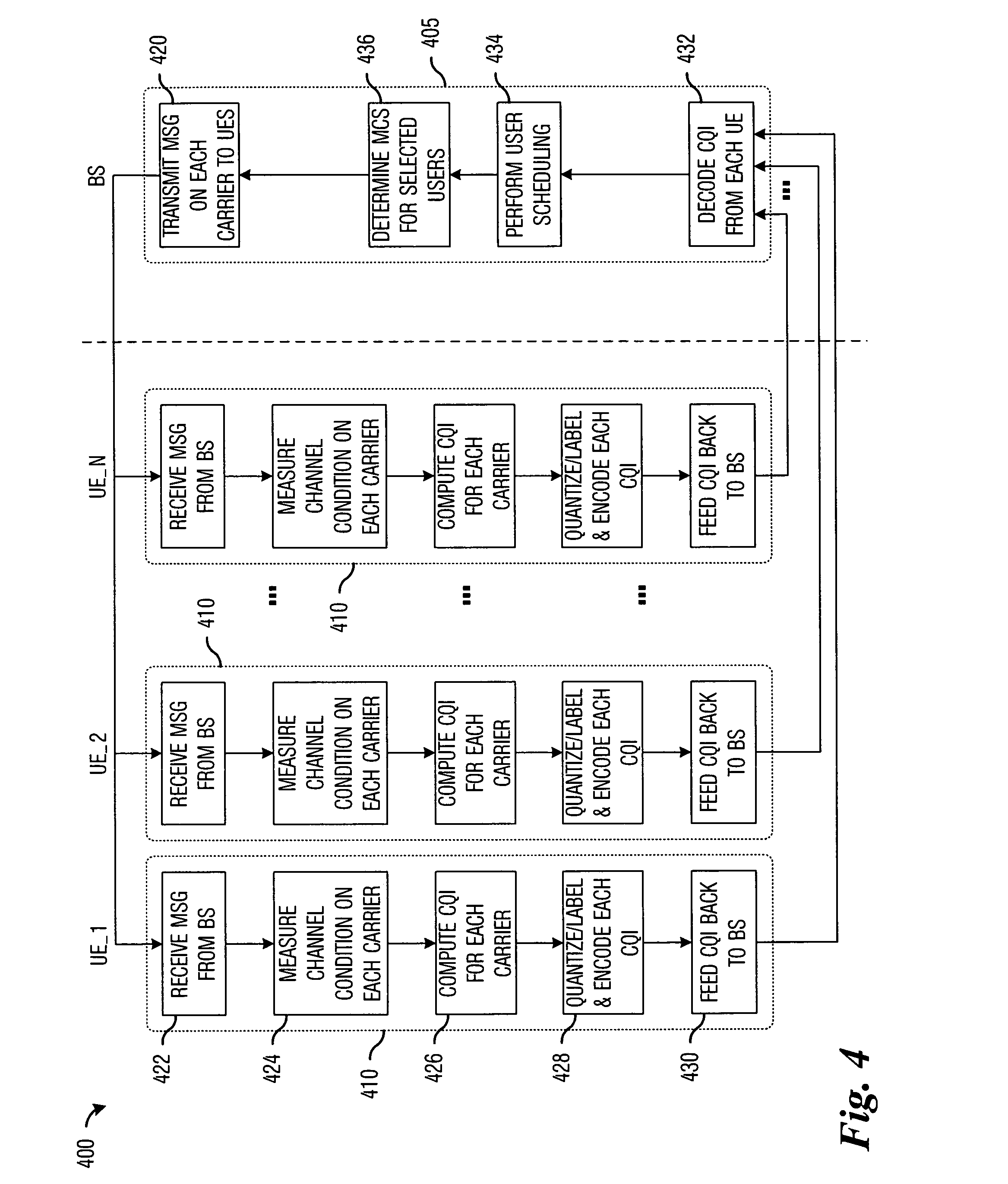
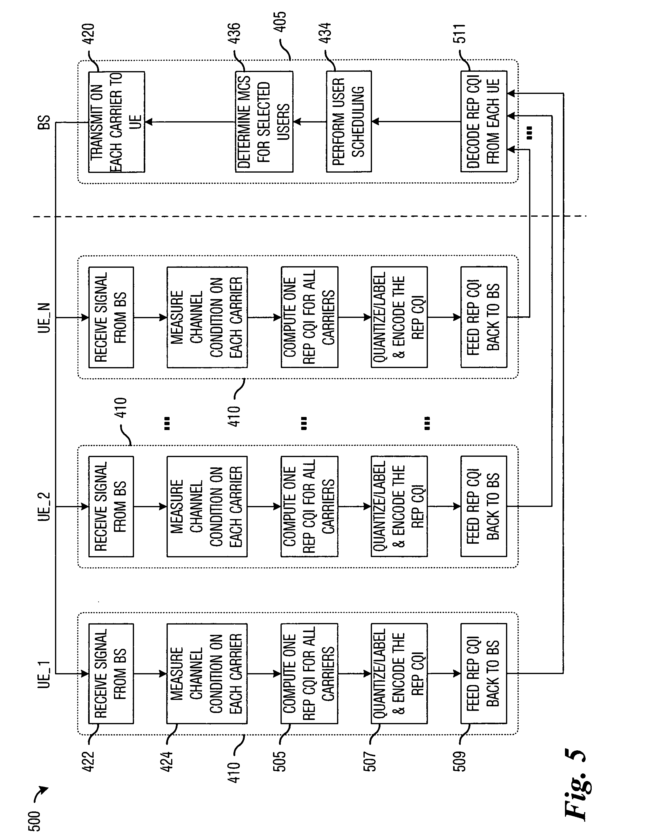
The present invention provides a method for improving retransmission performance in a multi-carrier communications system by exploiting diversity. This is achieved by measuring the channel condition for each carrier and computing a channel quality indicator based upon the measured channel condition. The computed channel quality indicator is then provided to the transmitter. This method allows for a more accurate estimation of the quality of individual carriers and reduces the need for special transmissions. The invention also allows for the use of actual transmissions on the carriers, improving the overall performance of the communications system by reducing overhead.

Problems solved by technology

One disadvantage of the prior art is that if the channels are not sufficiently close to one another in frequency, then a CQI computed for one channel may not be applicable to other channels.
Another disadvantage of the prior art is that even if the channels are sufficiently close to one another in frequency, the use of a CQI that was computed for a single channel by other channels only provides an approximation and not an accurate estimate.
The interferer may be sufficiently large to negatively impact the transmissions carried in the first channel.
Therefore, a CQI computed for the second channel does not accurately approximate the channel quality of the first channel.

Method used


Image

  • Method for channel quality indicator computation and feedback in a multi-carrier communications system
  • Method for channel quality indicator computation and feedback in a multi-carrier communications system
  • Method for channel quality indicator computation and feedback in a multi-carrier communications system

Examples


Embodiment Construction

[0022] The making and using of the presently preferred embodiments are discussed in detail below. It should be appreciated, however, that the present invention provides many applicable inventive concepts that can be embodied in a wide variety of specific contexts. The specific embodiments discussed are merely illustrative of specific ways to make and use the invention, and do not limit the scope of the invention.

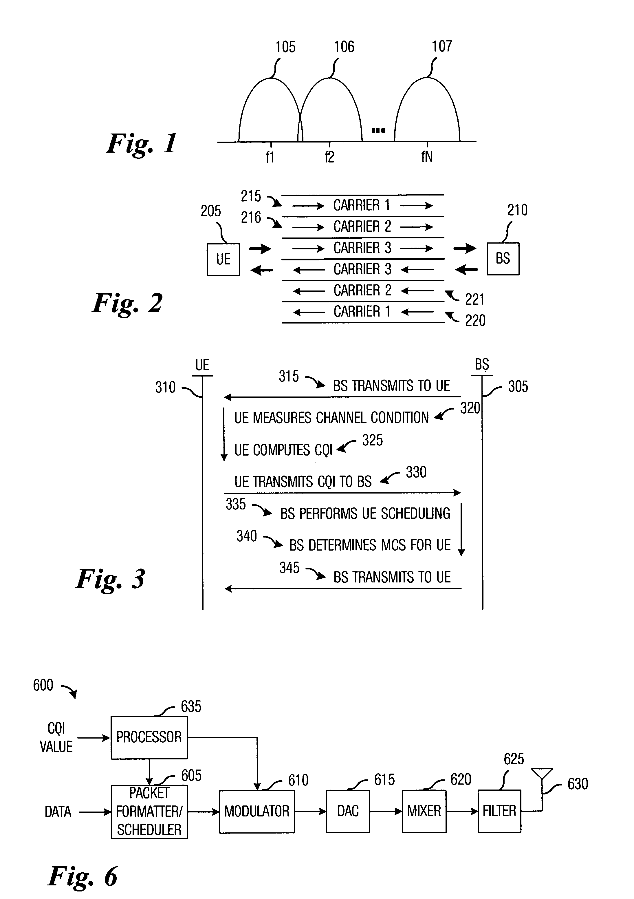
[0023] The present invention will be described with respect to preferred embodiments in a specific context, namely a three-carrier multi-carrier communications system, such as 3xEV-DV, which is an extension to a single carrier communications system 1xEV-DV. 1xEV-DV is an evolution of CDMA2000 and supports voice and high-speed data using code-division multiple access (CDMA). The invention may also be applied, however, to multi-carrier communications systems in general, with no limit on the number of carriers, such as NxEV-DV (an N-carrier EV-DV system) and an extension to 1x...


PUM


Abstract

Method for computing and transmitting channel quality information in a multi-carrier communications system. A preferred embodiment comprises receiving a transmission from a transmitter, wherein the transmission occurs over a plurality of carriers, measuring a channel condition for each carrier in a plurality of carriers, computing a channel quality indicator based upon the measured channel condition, and providing the channel quality indicator to the transmitter. The channel quality indicator can be used at the transmitter to schedule transmissions to various users in the multi-carrier communications system to maximize utilization of the carriers as well as overall network performance.

Description

[0001] This application claims the benefit of U.S. Provisional Application No. 60 / 555,728, filed Mar. 22, 2004, entitled “Methods of Channel Quality Indicator (CQI) Computation and Feedback for 3xEV-DV” which application is hereby incorporated by reference.TECHNICAL FIELD [0002] The present invention relates generally to a method for digital communications, and more particularly to a method for computing and transmitting channel quality information in a multi-carrier communications system. BACKGROUND [0003] Communications channel (or simply, channel) quality can have a significant impact on the performance of a wireless communications system (communications system). A communications system with channels with high channel quality can transfer data at a higher rate and with a lower latency than a communications system with channels with low channel quality. Given a pair of communications channels in a communications system, a communications channel with high channel quality will more ...

Claims


Application Information

Patent Timeline
Patent Type & Authority Applications(United States)
IPC IPC(8): H04J1/16H04J3/14H04L5/02H04L27/26
CPCH04L1/0003H04L1/0009H04W72/1231H04L27/2608H04W24/10H04L5/023H04W72/542
Inventor ONGGOSANUSI, EKO N.DABAK, ANAND G.SCHMIDL, TIMOTHY M.PAPASAKELLARIOU, ARISHUI, YAN
Owner TEXAS INSTR INC
Learn More