Optical pickup device

a pickup device and optical technology, applied in the direction of disposing/mounting heads, instruments, data recording, etc., can solve the problems of deterioration of the characteristic of displacing the object lens, deterioration of the reading and writing function of the optical pickup device, and increase the dispersion of the filling amount, so as to achieve the effect of convenient filling

Inactive Publication Date: 2005-09-22
FUNAI ELECTRIC CO LTD
View PDF11 Cites 13 Cited by
  • Summary
  • Abstract
  • Description
  • Claims
  • Application Information

AI Technical Summary

Benefits of technology

[0010] According to the background art explained in reference to FIG. 4 or FIG. 5, the filling portion 71 for holding the damper member 8 is formed by the groove shaped vacant portion, the total of the groove shaped vacant portion is opened at the side face of the fixed support member 2 and therefore, there is achieved an advantage that the open port 75 can widely be ensured and the damper member 8 is easy to fill, in contrast thereto, it is difficult to fill each of the filling portions 71 having the same volume with a constant amount of the damper member 8. That is, the volume of the damper member 8 is changed by being influenced by temperature of an operational environment or body temperature of an operator, further, a front and rear width a (refer to FIG. 4) of the open port 75 is provided with a width the same as a front and rear width of the groove shaped hollow portion fixed by the groove-like face 71, further, an up and down width b (refer to FIG. 5) of the open port 75 is provided with a width the same as an up and down width of the groove shaped hollow portion and therefore, a layer surface 81 of the damper member 8 filled to the filling portion 71 by utilizing the open port 75 is molded in a recessed shape in an up and down direction at a location of the open port 75 (for example, upper two states of FIG. 5), or molded in a bulged shape (for example, a lower state of FIG. 5), further, the layer surface 81 is molded in a wavy shape in a front and rear direction at the location of the open port 75, and there is a concern that each of the filling portions 71 is difficult to be filled with the constant amount of the damper member 8. Further, when amounts of filling the damper member 8 to the individual faces 71 are significantly dispersed, operation of damping the individual wire members 6 is not uniformly achieved and a characteristic of displacing the movable lens holder 3 and therefore, the object lens 31 is deteriorated, which amounts to a deterioration in the reading and writing function by the optical pickup device.

Problems solved by technology

Further, when amounts of filling the damper member 8 to the individual faces 71 are significantly dispersed, operation of damping the individual wire members 6 is not uniformly achieved and a characteristic of displacing the movable lens holder 3 and therefore, the object lens 31 is deteriorated, which amounts to a deterioration in the reading and writing function by the optical pickup device.
However, since the front and rear width of the slit becomes the width the same as that of the front and rear width of the recess portion and therefore, it can be said that non-uniformity of a shape in the front and rear direction of the layer surface of the damper member is not restrained and the layer surface is molded in the wavy shape in the front and rear direction to cause to increase a dispersion in the filling amount.
Further, it is known that the characteristic of displacing the object lens is deteriorated and the reading and writing function by the optical pickup device is deteriorated also by the dispersion in the filling amount caused by molding the layer surface of the damper member in the wavy shape in the front and rear direction.
Further, it is also known that by forming the front and rear width of the slit by the width the same as that of the front and rear width of the recess portion, when the damper member is injected to one point (one portion) in the front and rear direction of the slit, there is a concern of bringing about a drawback of leaking out the damper member injected to the recess portion from other portion of the slit.

Method used


Image

  • Optical pickup device
  • Optical pickup device
  • Optical pickup device

Examples


Embodiment Construction

[0021] Now referring to the attached drawings as the occasion demands, an explanation will be given of a best mode for carrying out the invention.

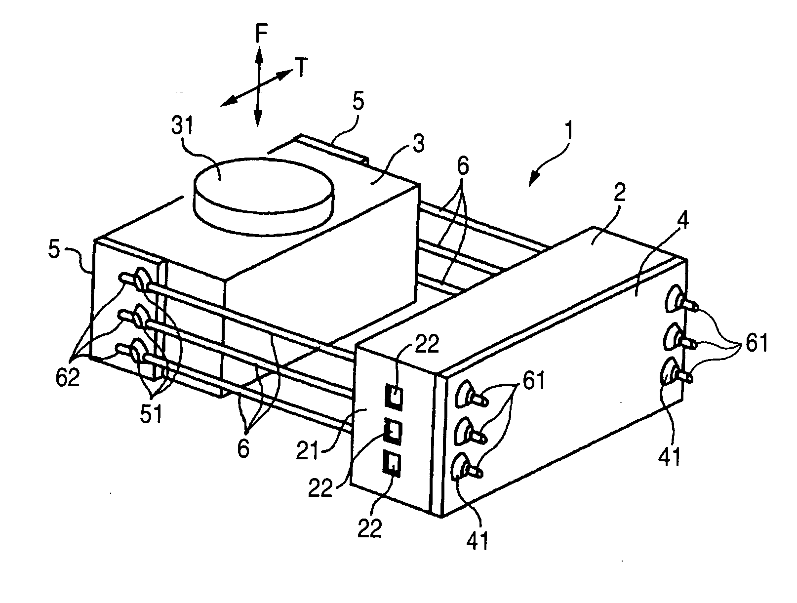
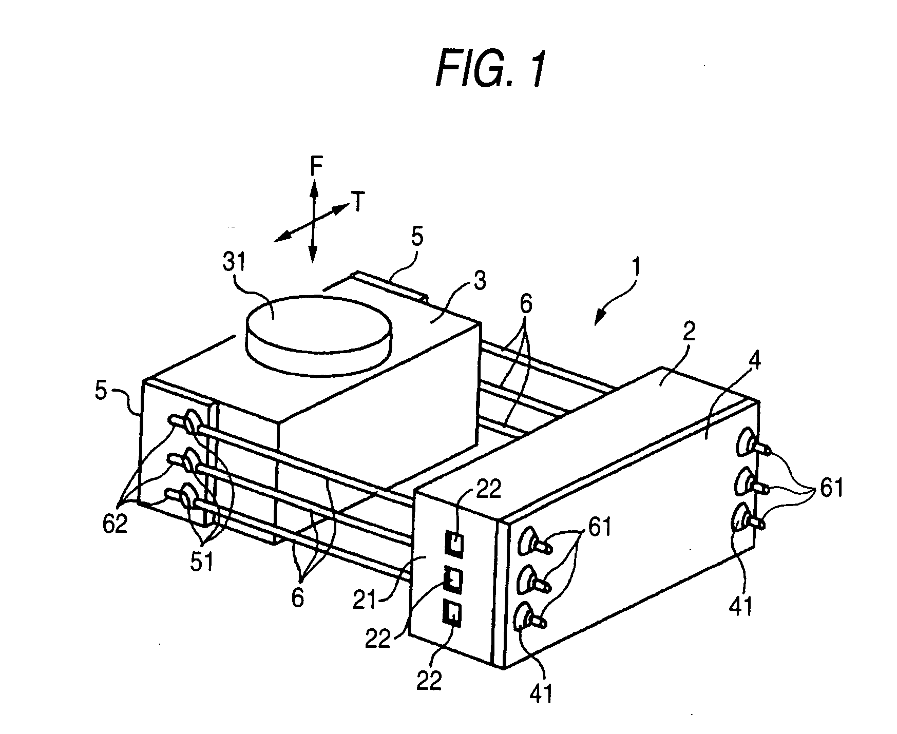
[0022]FIG. 1 is an outline perspective view of the lens unit 1 adopted in the optical pickup device according to the invention, FIG. 2 is a partially broken front view showing to enlarge the essential portion of the fixed support member 2, and FIG. 3 is an outline perspective view showing to enlarge the essential portion of the fixed support member 2.

[0023] A point of differing the lens unit 1 of FIG. 1 from the lens unit 1 explained in reference to FIG. 4 resides in that the fixed support member 2 is integrally formed with a lid portion 21 and the lid portion 21 is provided with a damper member filling port 22. The other items, for example, that the fixed support member 2 of the lens unit 1 is fixed to the base (not illustrated) driven to travel in the radius direction of the disk, that the movable lens holder 3 is mounted with the plur...


PUM

PropertyMeasurementUnit
elasticityaaaaaaaaaa
widthaaaaaaaaaa
shapeaaaaaaaaaa

Abstract

Other end portion of a wire member 6 having elasticity one end portion of which is fixed to a fixed support member 2 is fixed to a movable lens holder 3 having an object lens 31. The wire member 6 is arranged to penetrate through a layer of a damper member 8 filled to a filling portion 7 of the fixed support member 2. The filling portion 7 is formed by a groove-like face 71 and an inner face 21a of a lid portion 21. The lid portion 21 is provided with a damper member filling port 22. A front and rear width c and an up and down width d of the damper member filling port 22 are narrower than a front and rear width a and an up and down width b of a groove shaped hollow portion.

Description

BACKGROUND OF THE INVENTION [0001] 1. Field of the Invention [0002] The present invention relates to an optical pickup device mounted to an optical disk drive, in details, relates to an optical pickup device having a lens unit in which a movable lens holder having an object lens is supported by a wire member having elasticity extended from a fixed support member displaceably in a cantilever state. [0003] 2. Description of the Related Art [0004] An optical pickup device mounted to an optical disk drive is used for writing or reading data by converging laser light to a disk face as a record medium and is provided with a function of controlling a position of an object lens in a focus direction or in a tracking direction in accordance with face swinging or eccentricity in rotating a disk. [0005]FIG. 4 shows an outline of a lens unit 1 are adopted in an optical pickup device of a background art. The lens unit 1 of the drawing is mounted to a base (not illustrated) driven to travel in a r...

Claims


Application Information

Patent Timeline
Patent Type & Authority Applications(United States)
IPC IPC(8): G11B7/00G11B7/09
CPCG11B7/0933G11B7/0932
Inventor KOJIMA, TOGO
Owner FUNAI ELECTRIC CO LTD
Why Eureka
Try Eureka