
Vacuum excavation suction hose attachment

a vacuum hose and suction hose technology, applied in the field of hose attachments, can solve the problems of limiting the maximum size of debris entering the vacuum hose, affecting the velocity of air and debris travel, etc., and achieve the effect of reducing the size of the opening

Inactive Publication Date: 2005-09-29
BUCKNER LYNN A
View PDF15 Cites 3 Cited by
  • Summary
  • Abstract
  • Description
  • Claims
  • Application Information

AI Technical Summary

Benefits of technology

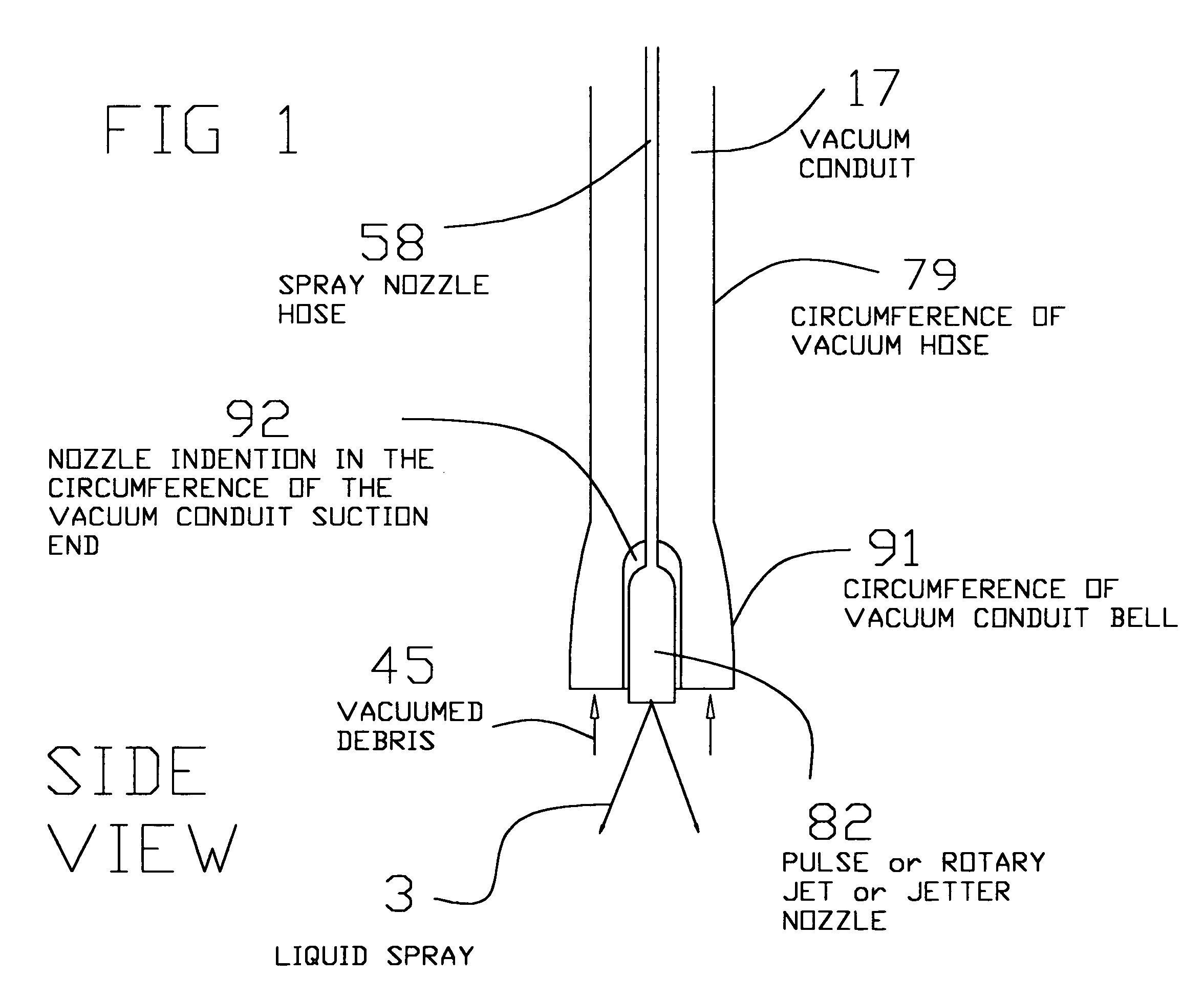
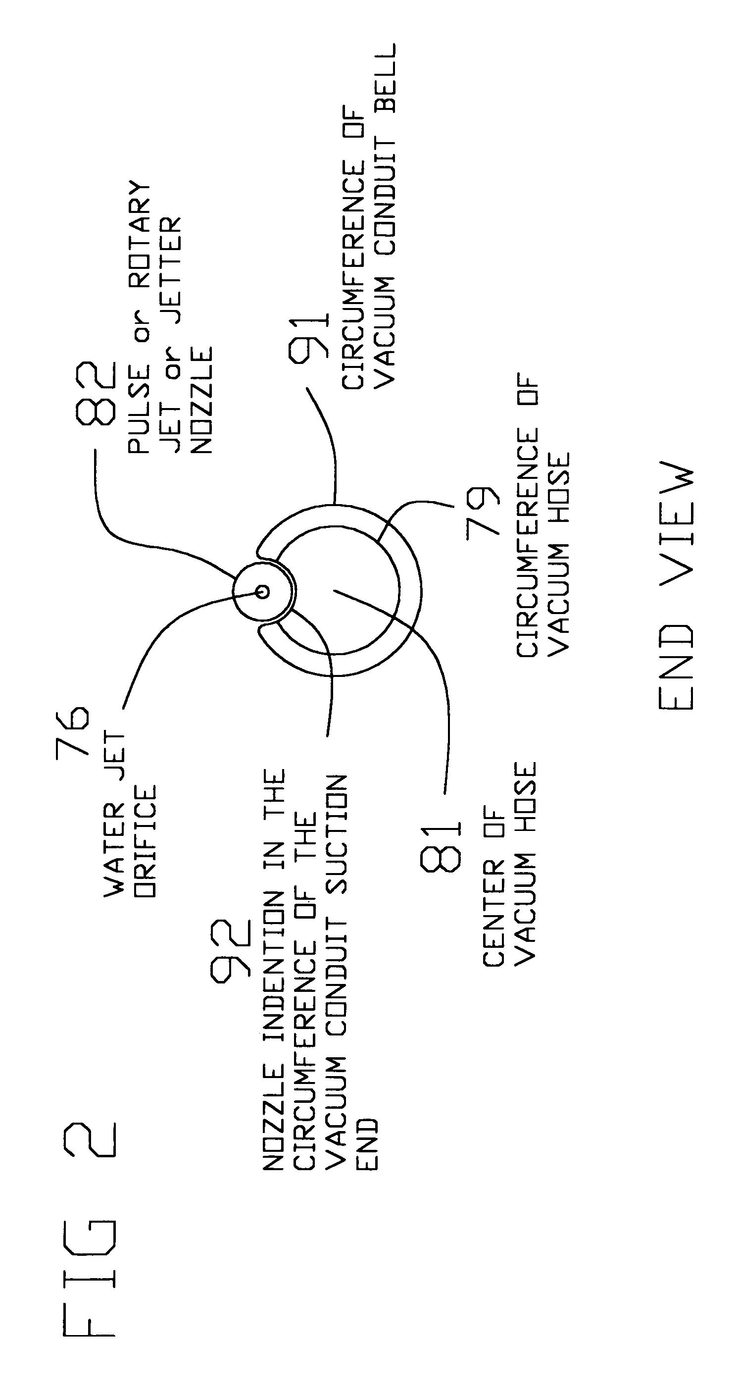
[0007] In accordance with one embodiment of the invention, the spray nozzle is housed within an indention on the outside surface of the suction end of the vacuum conduit. The indention reduces the size of the opening in the suction end, and thus affects the velocity of air and debris travel and limits the maximum debris size entering the vacuum hose.

Problems solved by technology

The indention reduces the size of the opening in the suction end, and thus affects the velocity of air and debris travel and limits the maximum debris size entering the vacuum hose.

Method used


Image

  • Vacuum excavation suction hose attachment
  • Vacuum excavation suction hose attachment
  • Vacuum excavation suction hose attachment

Examples


Embodiment Construction

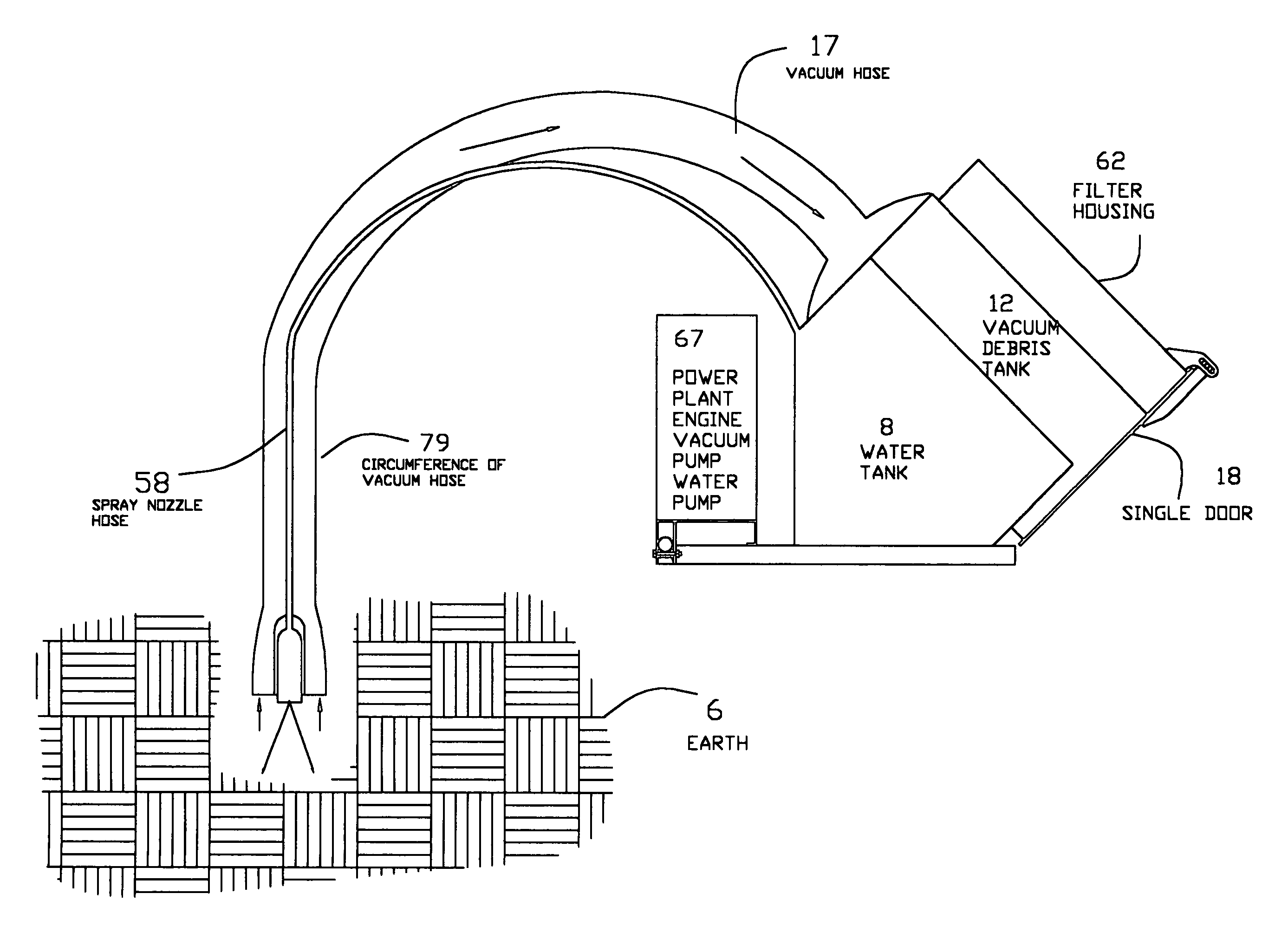
[0021] Referring now to the drawings, FIG. 1 is a cross section side elevation of a vacuum hose 17 which may be used to vacuum excavated dirt or earthen material. The circumference wall 79 of the vacuum hose 17 has been increased at the suction inlet to form a bell 91 shaped configuration. The bell circumference 91 is larger than the vacuum hose circumference 79 thus increasing the inlet area. An indention 92 is made into the bell circumference 91. The ratio between the vacuum hose circumference 79, the bell circumference 91 and the size of the indention 92, affects the area of the suction inlet of the vacuum hose 17 thus affecting the velocity of air and debris travel at that point. Various desired velocity characteristics may be achieved by manipulating the above mentioned ratios. Various debris 45 are vacuumed more effectively at different velocities thus the above mentioned ratios may be predetermined for best efficiency of a given debris 45 to be vacuumed.

[0022] The indention ...


PUM


Abstract

Dirt or earthen material may be made more vacuum able by first loosening dirt with a force of air or liquid. A water nozzle spray on dirt both loosens and dilutes the dirt into mud, which may then be easily vacuumed. The two-step process may be incorporated into a one-step process by attaching the water spray nozzle onto an indention in the circumference of the vacuum conduit. Making an indention in the circumference of the vacuum conduit reduces the outside protrusion of the nozzle, focuses the nozzle spray toward the entrance of the vacuum hose, thus efficiently loosening dirt directly at the entrance of the vacuum hose suction end. The inward protrusion of the indention reduces the size of debris, which may enter the inlet of the vacuum conduit. Reducing the size of debris to less than the inside size of the vacuum hose reduces the occurrence of debris clogging in the vacuum hose. The suction end of a vacuum conduit may have the inlet edge rolled inward to reduce the maximum size of debris which may enter the vacuum hose.

Description

FIELD OF THE INVENTION [0001] This invention relates to a hose attachment and, more particularly, to a vacuum excavation suction hose attachment. DESCRIPTION OF RELATED ART [0002] It is known in the art to use multiple hoses with vacuum systems in order to apply various fluids to the area being vacuumed in order to aid in debris removal. [0003] Hughes et al. (U.S. Pat. No. 4,517,404) discloses one such system using one hose connected to a vacuum and a second hose used to spray a solution such as soap or water in order to create an emulsion with the dirt in the rug. [0004] One problem arising from the conventional art is when the debris being vacuumed has a wide range of size, the vacuum hose can become clogged from the larger particles. [0005] Another problem arising from the conventional art is the spray nozzle attachment can increase the overall size of the vacuum hose system, and may prevent access to smaller areas. SUMMARY OF THE INVENTION [0006] In order to overcome the problem...

Claims


Application Information

Patent Timeline
Patent Type & Authority Applications(United States)
IPC IPC(8): A47L9/02E02F3/92E21B37/00F16L11/22
CPCE02F3/925F16L11/22E21B37/00
Inventor BUCKNER, LYNN A.
Owner BUCKNER LYNN A
Learn More