Mobile crane with stationary counterweight

a mobile crane and counterweight technology, applied in the direction of cranes, load-engaging elements, transportation and packaging, etc., can solve the problem of high transportation costs

Inactive Publication Date: 2005-09-29
FRANZEN HANS PETER
View PDF12 Cites 14 Cited by
  • Summary
  • Abstract
  • Description
  • Claims
  • Application Information

AI Technical Summary

Benefits of technology

[0016] Alternatively, according to another exemplary embodiment of the invention, it is also possible to keep the connection between the boom and the foundation ...

Problems solved by technology

It is well known that wind power stations in particular are erected in regions which may be very difficult to access.
This results in the problem that simply for the e...

Method used


Image

  • Mobile crane with stationary counterweight
  • Mobile crane with stationary counterweight
  • Mobile crane with stationary counterweight

Examples


Embodiment Construction

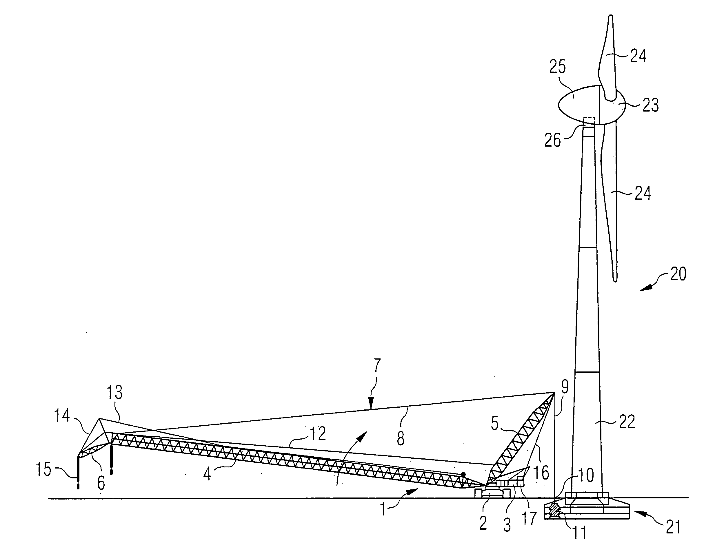
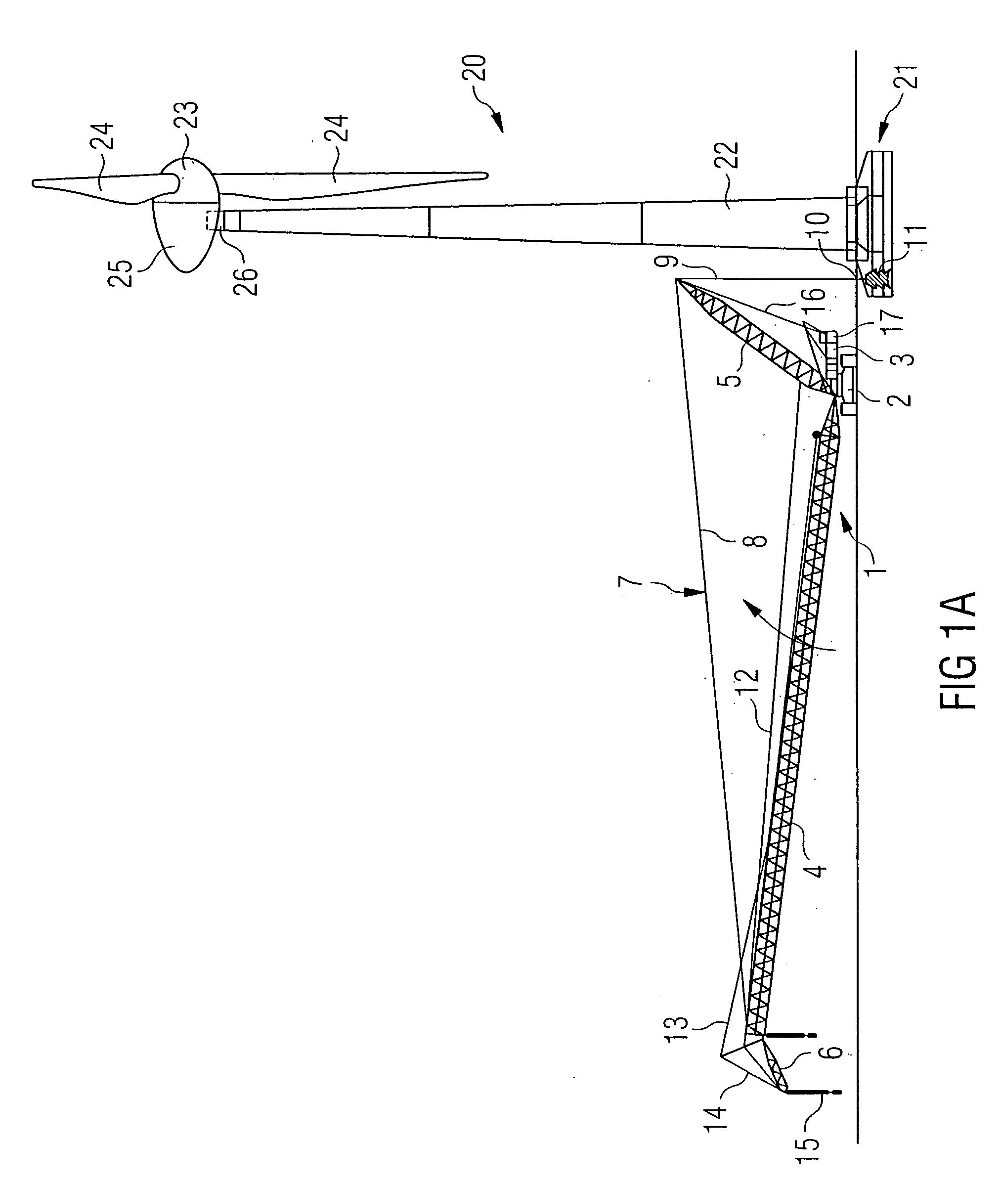
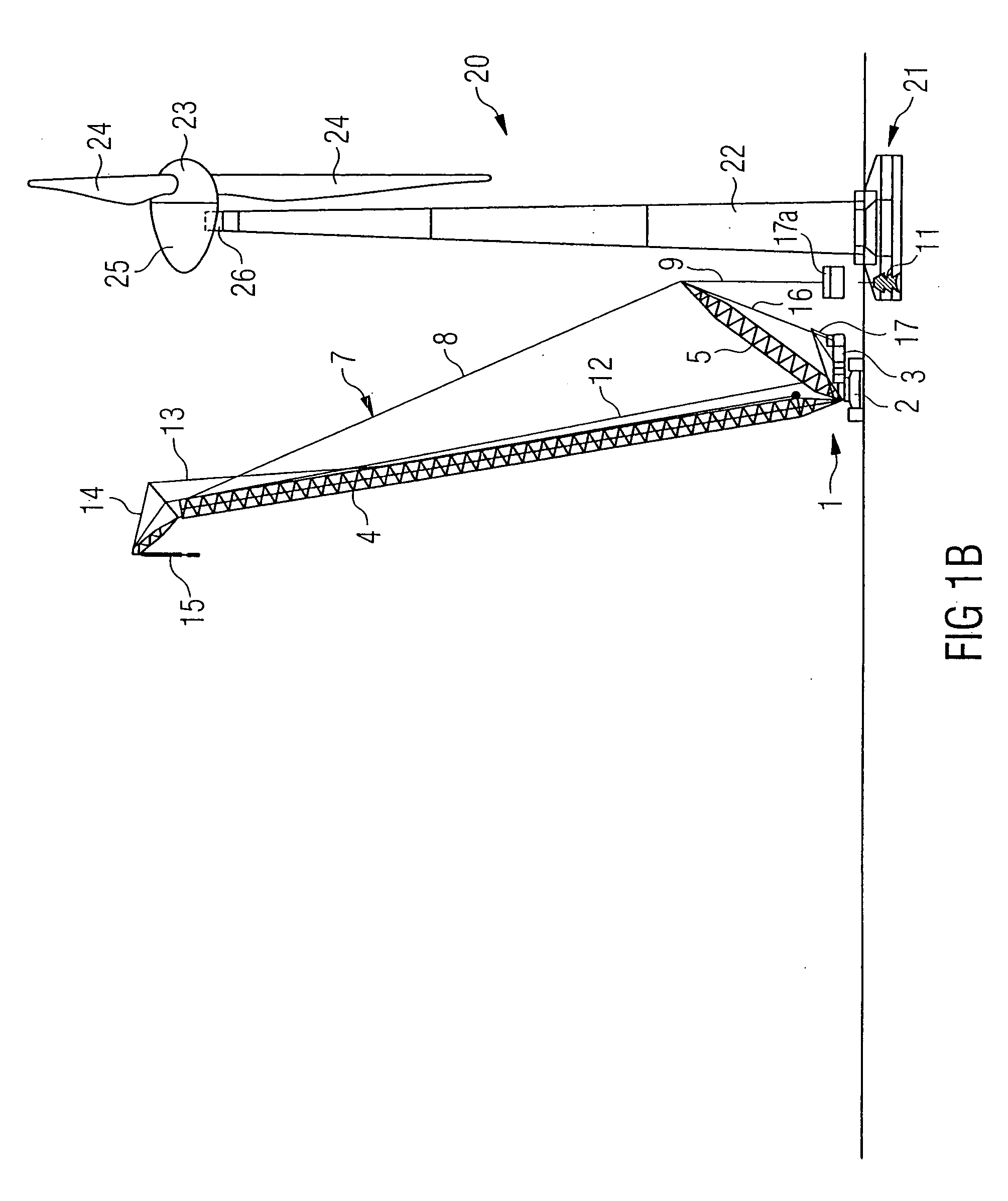
[0030]FIG. 1a shows a lattice boom crane 1 with a crawler-type carrier 2 and a superstructure 3 arranged on it, in an elevational view. A boom 4 is luffable on superstructure 3. Boom 4 consists of a plurality of lattice boom sections with a rigid fly jib 6 mounted at the top.

[0031] The lattice boom 1 shown here also has a derrick boom 5 which is connected, via a guying means 7, to a boom head of boom 4, to superstructure 3 and a foundation 21 of a wind power station 20. Guying means 7 comprises on the one hand a rope 8 which establishes a connection between the free end of derrick boom 5 and the head of boom 4. Moreover, the top end of derrick boom 5 is connected, via a rope 9 (which can also be a rod and / or a rope-rod combination) and via a connection means 10, to an anchoring means 11 in foundation 21 of wind power station 20. This will be described in more detail below. Derrick boom 5 is also connected to a counterweight 17 of mobile crane 1 via a rope 16.

[0032] Fly jib 6 is gu...


PUM


Abstract

The invention relates to a method of erecting or lowering a boom (4) of a mobile crane (1), comprising a crane carrier and, slewably arranged on said crane carrier (2), a superstructure (3), on which a boom (4) is luffably attached. With the erecting method according to the present invention the boom (4) is mounted on the superstructure (3) of the crane boom (1) in an essentially horizontal position. Then the boom (4) or the superstructure (3) is connected to a fixed foundation (21) which is anchored in the ground, and after this the boom (4) is erected to the desired luffed position while using the foundation (21) as a counterweight. For lowering the boom (4), the above steps basically have to be carried out in reversed order. The invention also relates to the use of a foundation (21) of a building under construction, such as a wind power station (20), and a mobile crane, in particular a lattice boom crane (1), suitable for carrying out the methods.

Description

CROSS REFERENCE TO RELATED APPLICATIONS [0001] This application claims the benefit of U.S. Provisional Patent Application Ser. No. 60 / 555,856, filed on Mar. 24, 2004 which is expressly incorporated herein, in its entirety, by reference.FIELD OF THE INVENTION [0002] The present invention relates to a method of erecting or lowering a boom of a mobile crane, in particular a lattice boom crane, comprising a crane carrier and, rotatable on the crane carrier, a superstructure on which the boom is attached to be luffed. The invention also relates to a fixed foundation of a building under construction—such as a wind power station—which is adapted to be connected in a suitable way to act as a counterweight for erecting a mobile crane. Finally the invention relates to a mobile crane having a luffing boom and a guying assembly connected to the boom. BACKGROUND OF THE INVENTION [0003] Mobile cranes of the above type, and in particular lattice boom cranes are used to lift heavy loads, sometimes ...

Claims


Application Information

Patent Timeline
IPC IPC(8): B66C23/26B66C23/34B66C23/74B66C23/82
CPCB66C23/185B66C23/82B66C23/74B66C23/34
Inventor FRANZEN, HANS-PETER
Owner FRANZEN HANS PETER
Why Eureka
Try Eureka