Fishing reel, fishing informatiom display apparatus, and fishing information display system

a technology of information display system and fishing reel, which is applied in the field of fishing reels, can solve the problems of affecting fishing, difficulty for the navigator who is far from the angler to acquire information, and inability of the navigator to suitably change the speed of the boat or the travel direction of the boa

Active Publication Date: 2005-09-29
SHIMANO INC
View PDF9 Cites 42 Cited by
  • Summary
  • Abstract
  • Description
  • Claims
  • Application Information

AI Technical Summary

Benefits of technology

[0009] An object of the present invention is to allow a navigator who is far from an angler to acquire information from the angler in a reliable manner.
[0012] A fishing reel according to a second aspect of the invention is the fishing reel according to the first aspect of the invention, in which the tension detector includes a torque sensor that detects a torque applied to the spool. In this case, for example, the torque sensor is provided on a spool shaft that rotates in cooperation with the spool, and detects the torque applied to the spool. Accordingly, it is possible to easily detect the tension applied to the fishing line corresponding to the torque applied to the spool.
[0013] A fishing reel according to a third aspect of the invention is the fishing reel according to the second aspect of the invention, further including a drag mechanism that brakes the rotation of the spool. The torque sensor detects the torque applied to the drag mechanism. In this case, for example, the torque applied to the drag mechanism such as a star drag attached to a handle shaft, or a lever drag attached to a spool shaft, is detected. Accordingly, it is possible to accurately detect the tension applied to the fishing line corresponding to the torque applied to the drag mechanism.
[0014] A fishing reel according to a fourth aspect of the invention is the fishing reel according to the third aspect of the invention, further including a one-way clutch that is adapted to selectively prohibit reverse rotation of the spool in a line-releasing direction. The torque sensor is attached between the one-way clutch and the drag mechanism. In this case, the torque sensor is attached to a spool shaft or a handle shaft between the one-way clutch and the drag mechanism, for example. Accordingly, it is possible to easily detect the torque applied to the drag mechanism.
[0015] A fishing reel according to a fifth aspect of the invention is the fishing reel according to the third or fourth aspect of the invention, in which the torque sensor includes a magnetostrictor magnetic that is designed to change its permeability depending on the torques applied to the drag mechanism, and a detection coil that is provided in a periphery of the magnetostrictor and configured to electrically detect the change in the magnetic permeability. In this case, since the torque can be detected only by providing a magnetostrictor that can be composed of a thin film or the like on a spool shaft or a handle shaft, and the detection coil in its periphery, it is not necessary to provide an electric device on a rotation part. Accordingly, it is possible to detect the torque in a non-contact manner. As a result, it is possible to provide easy electric wiring of the torque sensor, and compact construction of torque sensor.

Problems solved by technology

Accordingly, it is difficult for the navigator who is far from the angler to acquire the information, in the case, for example, where the angler is fighting as a fish strikes.
However, such information of the current fishing situation or whether a fish strikes is not conveyed to the navigator properly, the navigator cannot suitably change the boat speed, or the travel direction of the boat.
This may affect the fishing result.

Method used


Image

  • Fishing reel, fishing informatiom display apparatus, and fishing information display system
  • Fishing reel, fishing informatiom display apparatus, and fishing information display system
  • Fishing reel, fishing informatiom display apparatus, and fishing information display system

Examples


Embodiment Construction

[0043] Selected embodiments of the present invention will now be explained with reference to the drawings. It will be apparent to those skilled in the art from this disclosure that the following descriptions of the embodiments of the present invention are provided for illustration only and not for the purpose of limiting the invention as defined by the appended claims and their equivalents.

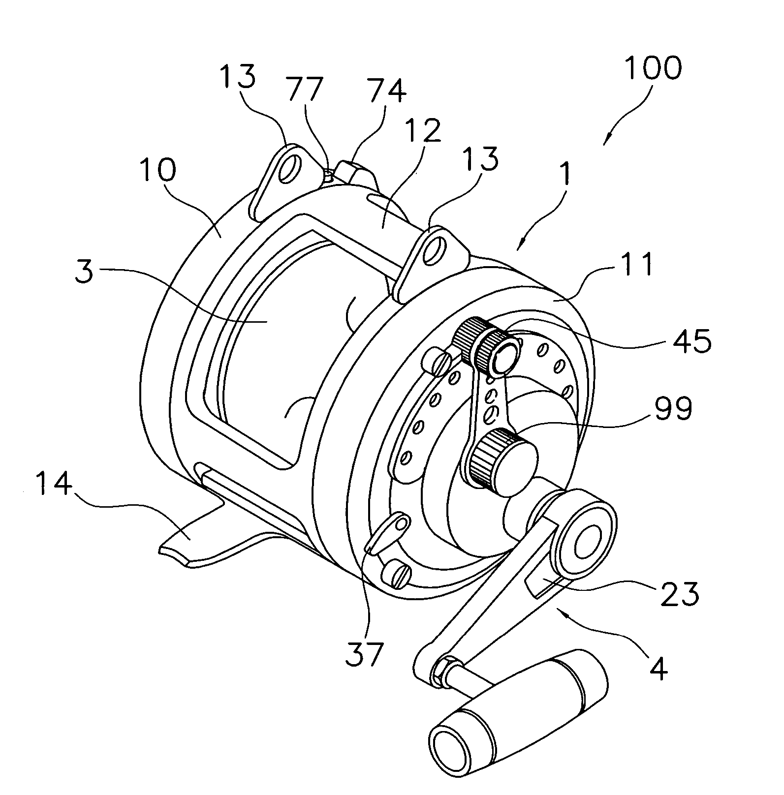
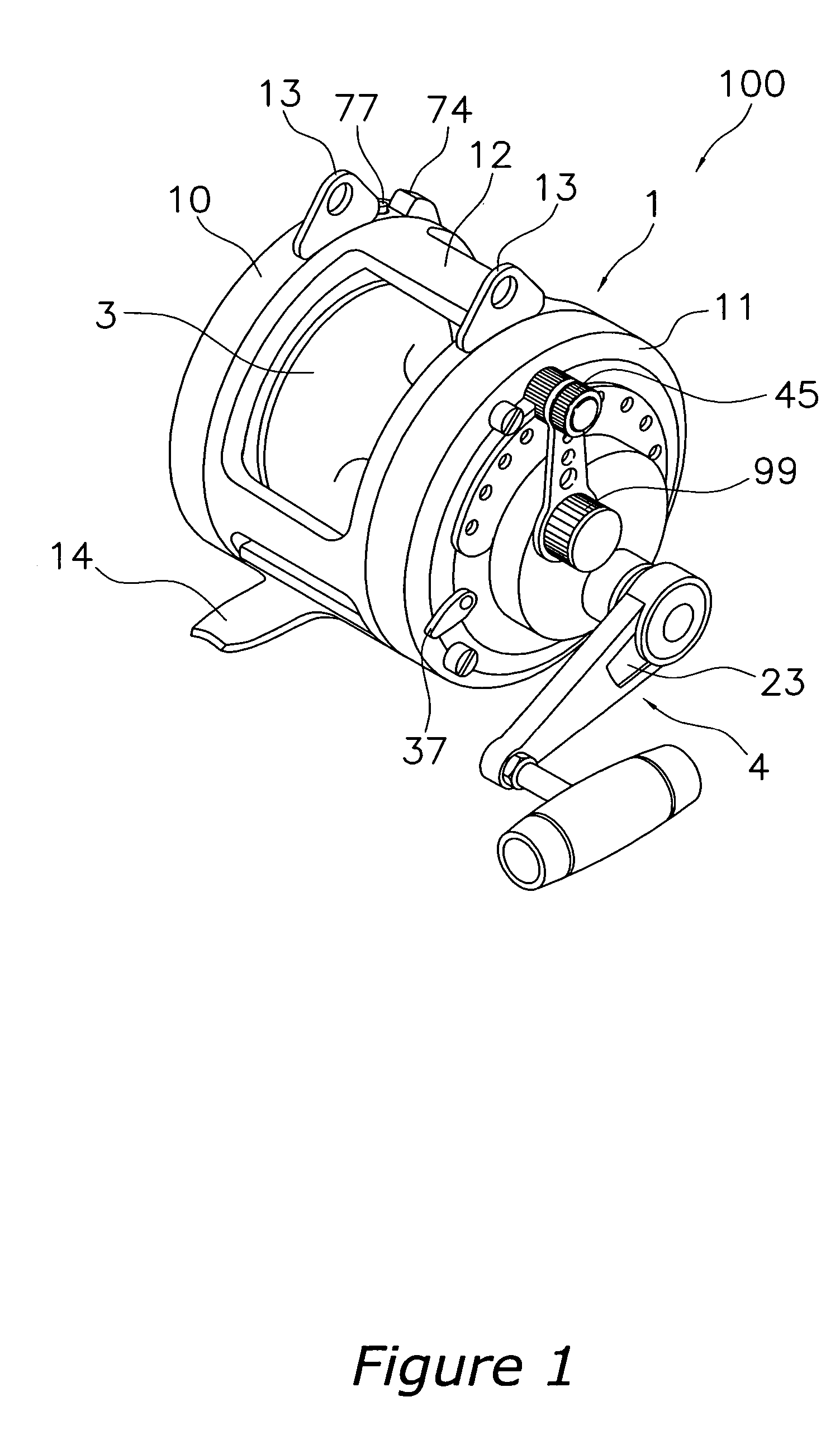
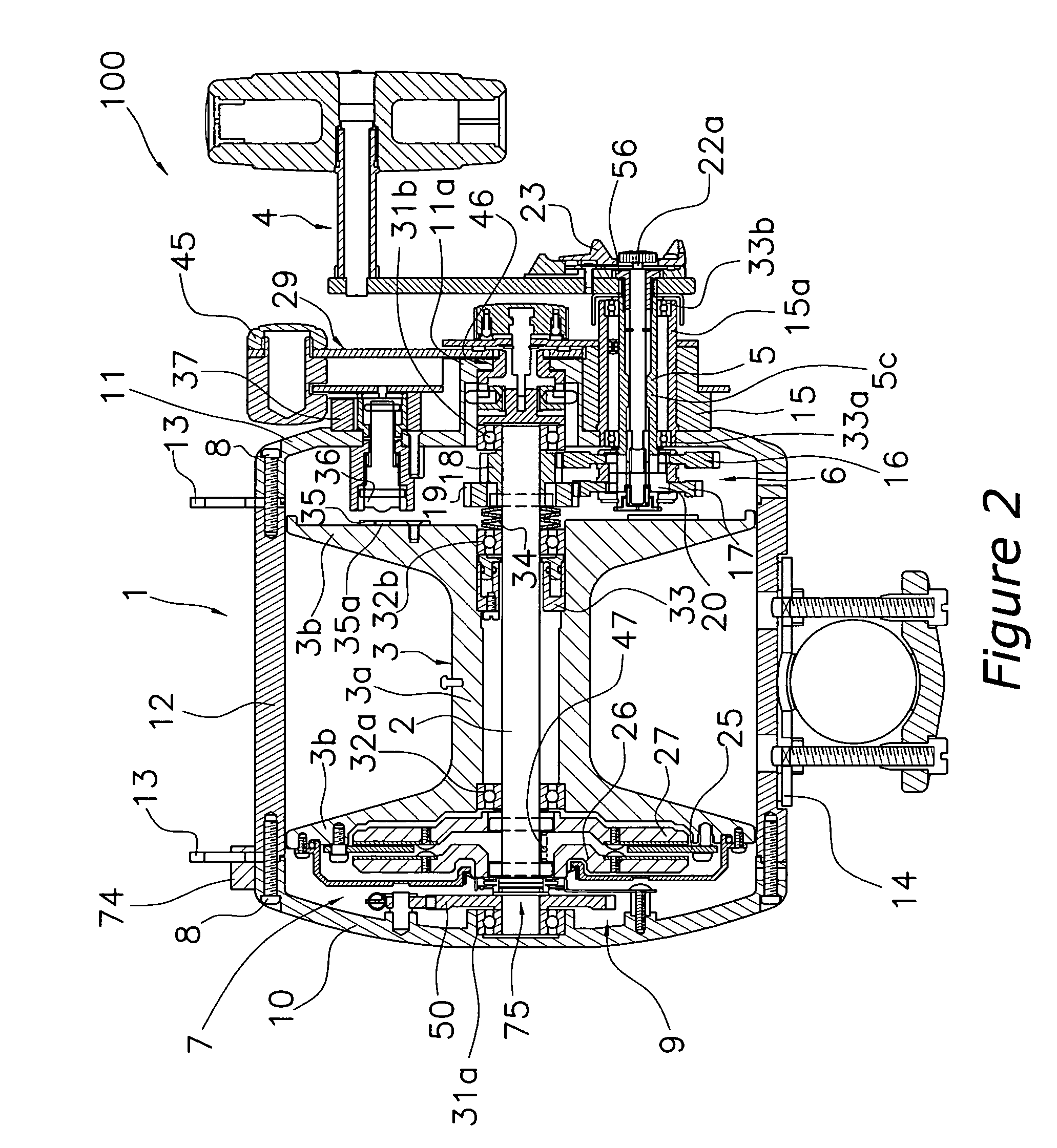
[0044] A fishing reel 100, which is in accordance with one embodiment of the present invention, is a large dual-bearing reel used for trolling, as shown in FIGS. 1 and 2. A dual-bearing reel 100 is furnished with: a cylindrical reel unit 1, a spool shaft 2 mounted rotatably in the central part of the reel unit 1, a spool 3 rotatably but axially immovably supported on the spool shaft 2, and a handle 4 disposed laterally on the reel unit 1. Likewise, within the reel unit 1 interior, the fishing reel 100 is furnished with: a torque-transmitting mechanism 6 that transmits torque from the handle 4 to ...


PUM


Abstract

A fishing reel has a reel unit that is mounted on the fishing rod, a spool that is rotatably attached to the reel unit, a tension detector that detects tension applied to the said fishing line, and a communication portion that transmits to a fishing information display apparatus data of the tension applied to the fishing line detected by the tension detector. The fishing information display apparatus is provided externally of a fishing reel, and receives data communicated from the fishing reel. The fishing information display apparatus includes a body member, a display portion provided in the body member, a communication portion that receives from the fishing reel data of the tension applied to the fishing line, and a controller that is displays on the display portion the data of tension received from the fishing reel. A navigator away from an angler can certainly have information of the fishing situation.

Description

BACKGROUND OF THE INVENTION [0001] 1. Field of the Invention [0002] The present invention relates to a fishing reel. More specifically, the present invention relates to a fishing reel that is adapted to be attached to a fishing rod for winding and releasing fishing line. [0003] 2. Background Information [0004] Generally, a fishing reel has a reel unit, a spool rotatably attached to the reel unit, and a handle for rotating the spool. The spool is attached to a spool shaft supported by the reel unit. The handle is non-rotatably attached to a handle shaft, which is disposed in parallel with the spool shaft. [0005] In this type of fishing reel, a trolling reel, which is a relatively large dual-bearing reel for so-called big game fishing of big fish such as swordfish and tuna, is known. Japanese Patent Application Publication 2000-262196 discloses an example of such trolling reel. [0006] In fishing with this type of trolling reel, an angler catches a fish by trailing terminal tackle conn...

Claims


Application Information

Patent Timeline
Patent Type & Authority Applications(United States)
IPC IPC(8): A01K89/00A01K89/015
CPCA01K89/015A01K89/00A01K97/12A01K89/05A01K89/01555A01K89/0192H01L21/67271
Inventor NAKAGAWA, SHOUJIIKUTA, TAKESHIKURIYAMA, HIROAKIKAWASAKI, KEN'ICHI
Owner SHIMANO INC
Why Eureka
Try Eureka