Two-sided deployable thermal radiator system and method

a thermal radiator and deployable technology, applied in the field of spacecraft, can solve the problems of not being developed and two-sided deployable thermal radiators, and achieve the effects of dissipation of heat, increased capability, and improved service li

Active Publication Date: 2005-09-29
MAXAR SPACE LLC
View PDF0 Cites 12 Cited by
  • Summary
  • Abstract
  • Description
  • Claims
  • Application Information

AI Technical Summary

Benefits of technology

[0007] To accomplish the above and other objectives, the present invention provides for a spacecraft thermal radiator system that uses two-sided deployable thermal radiators that dissipate heat from both front and back surfaces thereof. The use of the two-sided deployable thermal radiators enables the thermal radiator system to have approximately 50% more capability than a system with just one surface exposed to dissipate heat.

Problems solved by technology

However, a two-sided deployable thermal radiator has heretofore not been developed.

Method used


Image

  • Two-sided deployable thermal radiator system and method
  • Two-sided deployable thermal radiator system and method
  • Two-sided deployable thermal radiator system and method

Examples


Embodiment Construction

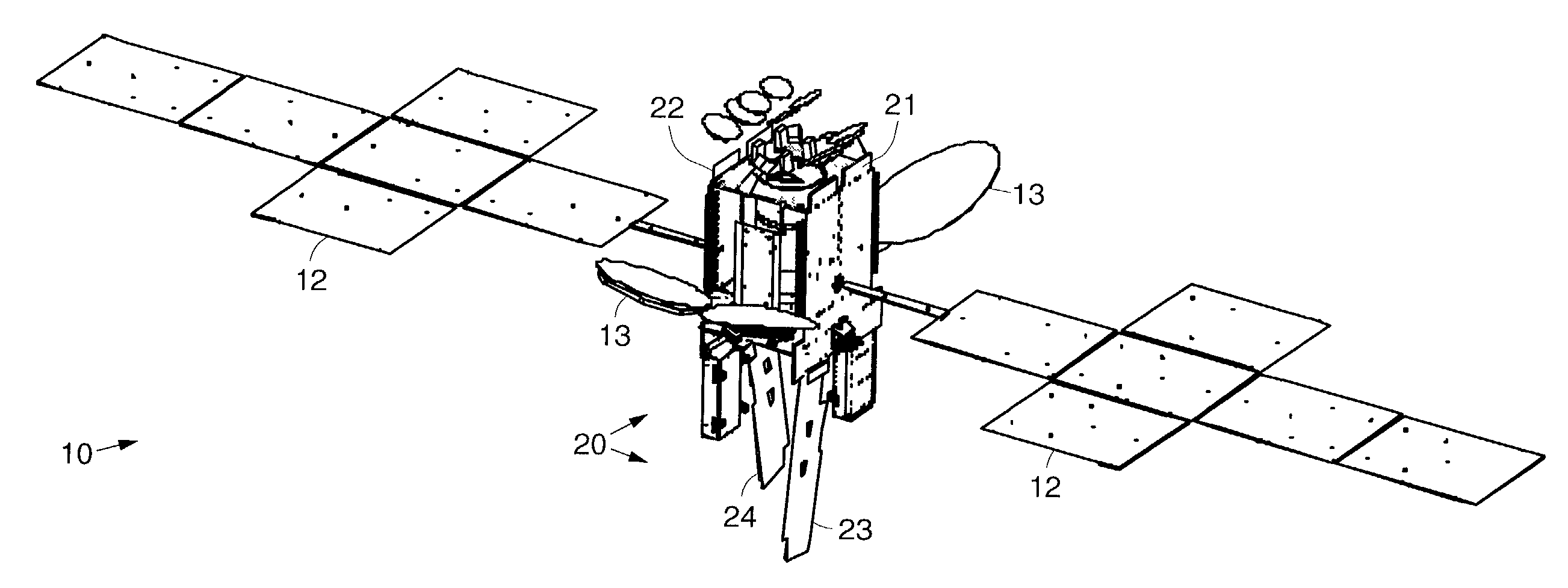
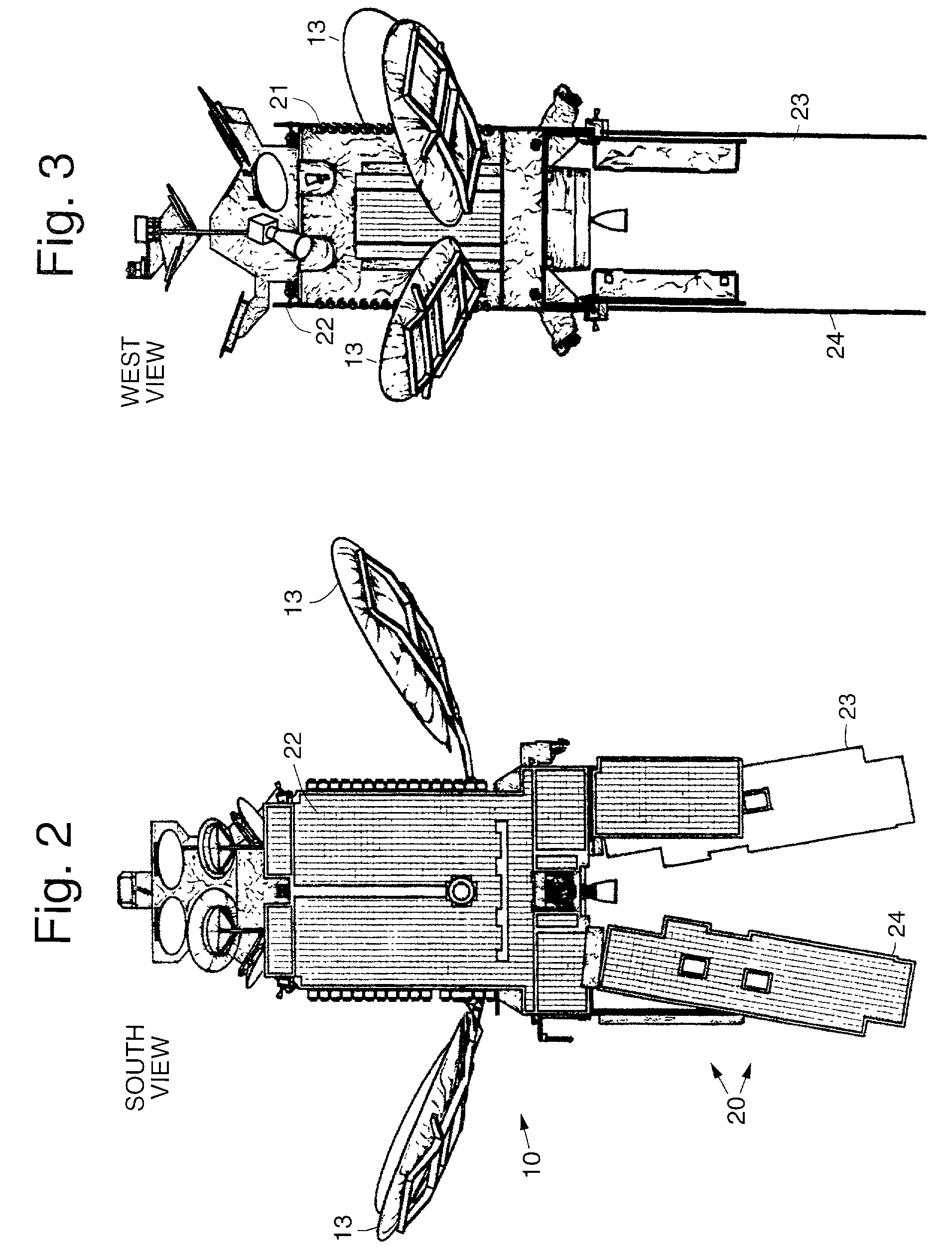
[0015] Referring to the drawing figures, FIG. 1 illustrates a spacecraft 10 employing an exemplary spacecraft thermal radiator system 20 in accordance with the principles of the present invention. FIGS. 2 and 3 illustrate south and west side views, respectively, of the spacecraft 10 and exemplary spacecraft thermal radiator system 20 shown in FIG. 1

[0016] The spacecraft 10 illustrated in FIG. 1 comprises a body 1 to which one or more solar arrays 12 are coupled. A plurality of antennas 13 are disposed on various faces of the body 11. The spacecraft 10 has a plurality of radiators 21-24, which in the exemplary embodiment comprise a north facing fixed payload radiator 21, a south facing fixed payload radiator 22, and a plurality of two-sided deployable radiators 23, 24.

[0017] The north facing fixed payload radiator 21 is thermally coupled to one of the two-sided deployable radiators 23, 24 by means of one or more coupling heat pipes 25, which are preferably loop heat pipes 25. Simila...


PUM


Abstract

A spacecraft heat dissipation method, and a spacecraft having an improved thermal radiator system that uses two-sided deployable thermal radiators that dissipates heat from both front and back surfaces thereof. The use of the two-sided deployable thermal radiators enables the thermal radiator system to have approximately 50% more heat dissipating capability than a system with just one surface exposed to dissipate heat. The spacecraft includes a body, one or more solar arrays, and the present radiator system which comprises opposite facing fixed payload radiators that are thermally coupled to selected ones of the deployable radiators by way of heat pipes. In an exemplary method a spacecraft is configured to have a body, one or more solar arrays opposite facing fixed payload radiators, and one or more two-sided deployable radiators selectively coupled to the fixed payload radiators. The spacecraft is launched into orbit. When in orbit, heat coupled to the opposite facing fixed payload radiators is transferred to the two-sided deployable radiators for radiation into space from both sides thereof.

Description

BACKGROUND [0001] The present invention relates generally to spacecraft, and more specifically to a two-sided deployable thermal radiator system and method for use on spacecraft. [0002] The assignee of the present invention manufactures and deploys spacecraft into geosynchronous and low earth orbits. Such spacecraft use a radiator system to dissipate heat. The radiator system transfers thermal energy to radiator panels where it is radiated into space. [0003] A deployable radiator used to shield the primary payload radiator in a stowed position to minimize transfer orbit heater power is disclosed by Caplin in U.S. Pat. No. 5,806,800 and Jones in U.S. Pat. No. 5,794,890. Various configurations of deployment radiator mechanisms and schemes are also disclosed by Cullimore in U.S. Pat. No. 5,177,901 and by Drolen in U.S. Pat. No. 5,787,969. However, a two-sided deployable thermal radiator has heretofore not been developed. [0004] Caplin and Jones describe deployable thermal radiators tha...

Claims


Application Information

Patent Timeline
Patent Type & Authority Applications(United States)
IPC IPC(8): B64G1/22B64G1/46B64G1/48B64G1/50
CPCB64G1/222B64G1/506B64G1/503
Inventor SEBATA, SUSANLOW, LENNY
Owner MAXAR SPACE LLC
Why Eureka
Try Eureka