Electromagnetic actuator

a technology of electromagnetic actuators and actuators, applied in the direction of valve details, valve arrangements, valve housings, etc., can solve the problems of oil leakage along the outer peripheral of the mounting hole, and achieve the effect of ensuring sealing performan

Inactive Publication Date: 2005-09-29
AISIN SEIKI KK
View PDF2 Cites 3 Cited by
  • Summary
  • Abstract
  • Description
  • Claims
  • Application Information

AI Technical Summary

Benefits of technology

[0008] Under the circumstances, the invention has been made in view of the above described problem, and it is one of technical objects...

Problems solved by technology

However, a seal structure of the electromagnetic valve in JP-A-10-122404 has the following problem.
However, in case where the fluid passage includes a plurality of oil passages which are radially formed on an outer peri...

Method used


Image

  • Electromagnetic actuator
  • Electromagnetic actuator
  • Electromagnetic actuator

Examples


Embodiment Construction

[0016] Referring now to the accompanying drawings, a description will be given in detail of a preferred embodiment of the invention.

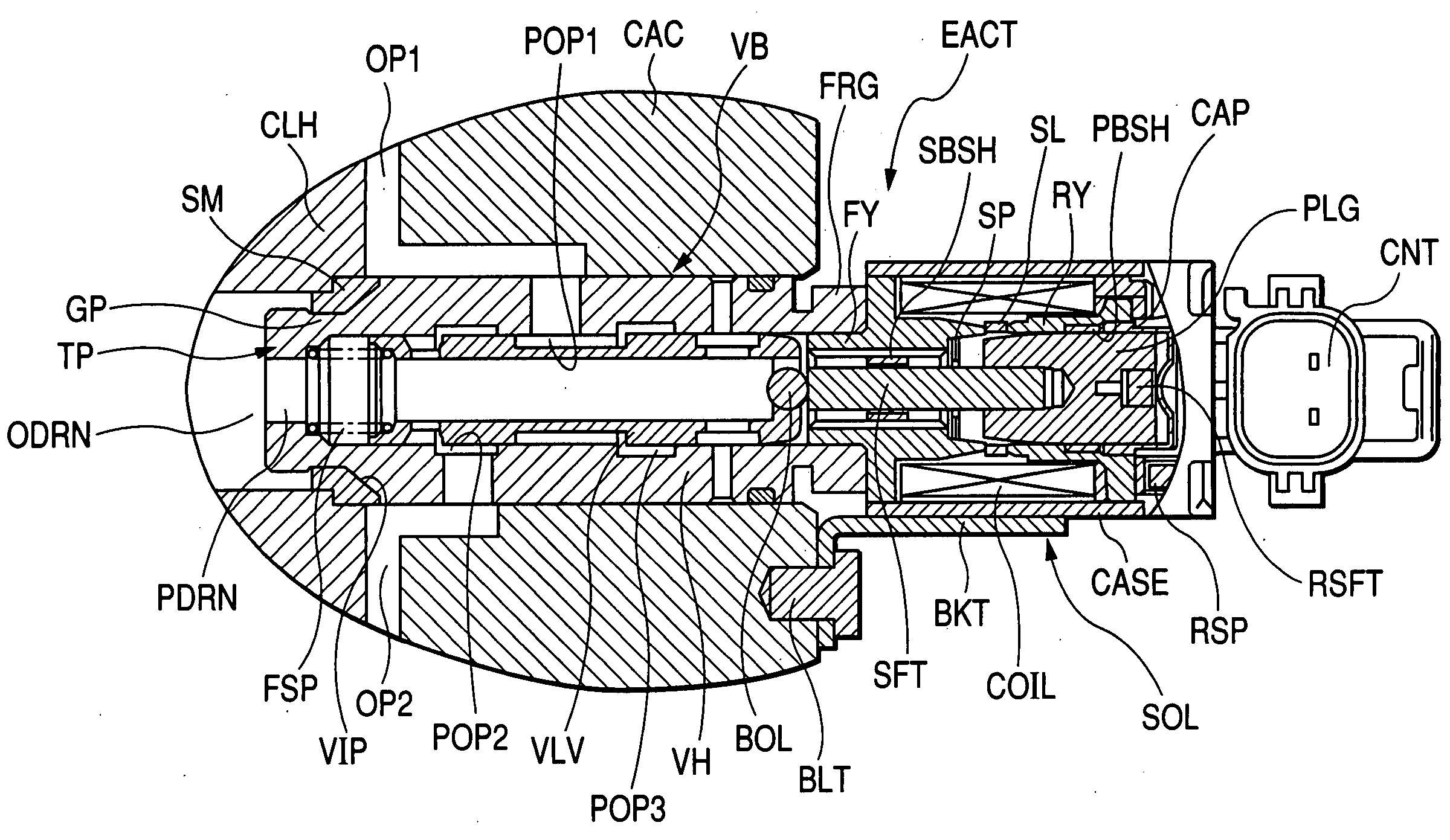
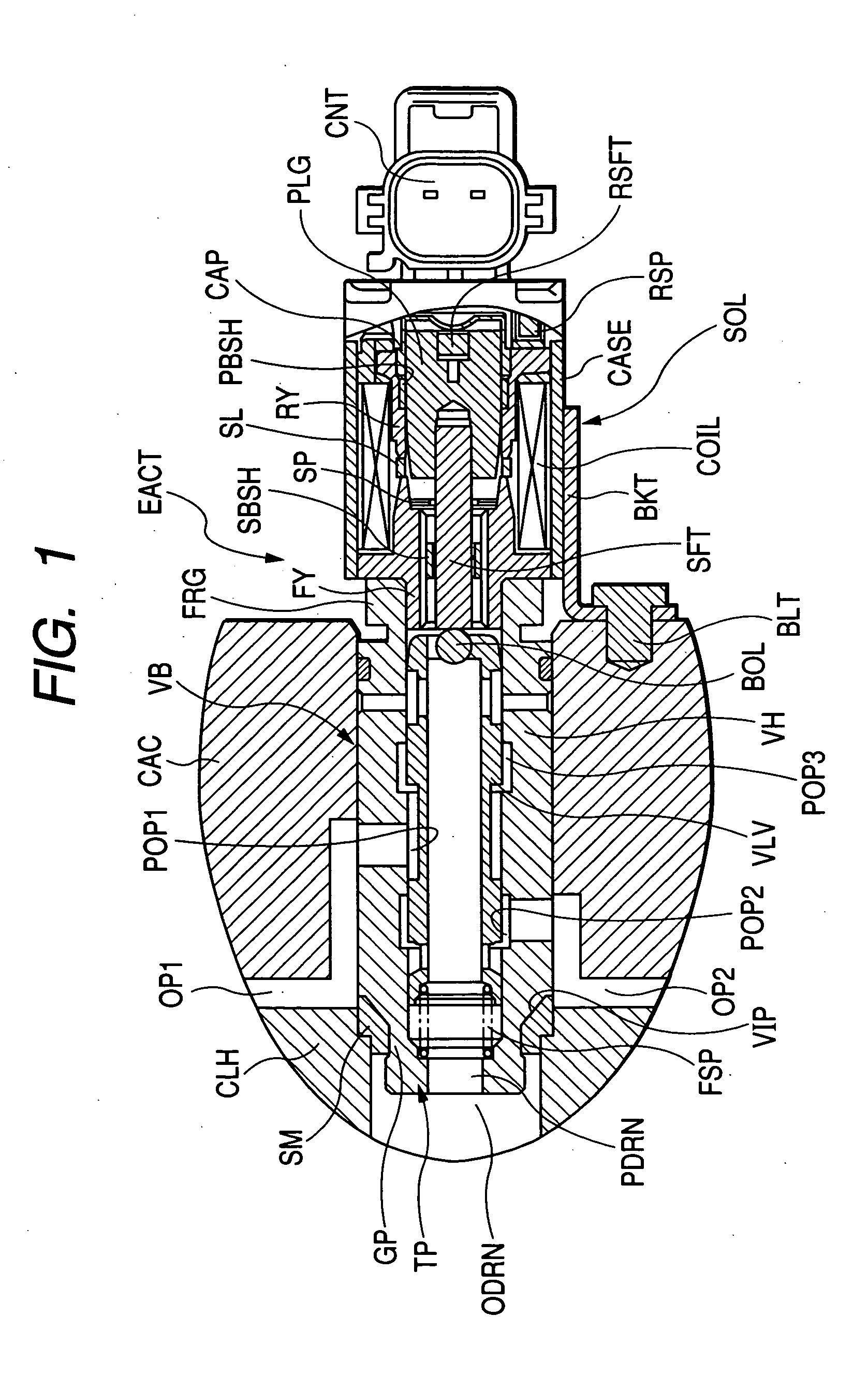
[0017]FIG. 1 is a fragmentary sectional view showing a structure of an electromagnetic actuator EACT according to the invention. The electromagnetic actuator EACT is mounted on a cylinder head CLH and a cam cover CAC of a main device, which is not shown, for conducting variable valve timing control of an internal combustion engine. The cylinder head CLH is provided with a return oil passage ODRN for oil returning from the electromagnetic actuator EACT to the main device, and the cam cover CAC is provided with a plurality of oil passages OP1, OP2, and OP3 which are radially formed with respect to an axis of a valve body part VB of the electromagnetic actuator EACT. The electromagnetic actuator EACT includes the valve body part VB, a solenoid part SOL, and a bracket BKT for installing the electromagnetic actuator EACT to the cam cover CAC. The bracket BK...


PUM


Abstract

An electromagnetic actuator includes: a valve body part formed in a substantially cylindrical shape and provided with: an opening to be connected to an external fluid passage; a valve accommodated in the valve body part; and a groove having an inclined face; a solenoid part that actuates a valve; and a seal member that is fitted on an outer peripheral of the inclined face to be urged in an axial direction of the valve body part.

Description

BACKGROUND OF THE INVENTION [0001] 1. Field of the Invention [0002] The present invention relates to an electromagnetic actuator including a solenoid for electromagnetically actuating a valve, and more particularly, to a seal structure for a fluid passage between a valve body part of the electromagnetic actuator and a member in which the valve body part is engaged and arranged. [0003] 2. Description of the Related Art [0004] Heretofore, an electromagnetic valve has been used as a control valve for a fluid which is employed for controlling vehicles, and various structures have been proposed considering adaptability to various kinds of devices (For example, See FIG. 1 of JP-A-10-122404). [0005] In JP-A-10-122404, an electromagnetic valve 10 including a valve body part 14, a solenoid part 16, and an installing bracket 18 is disclosed. On occasion of assembling the electromagnetic valve 10, in order to position the valve body part 14 around an axis according to hydraulic devices having ...

Claims


Application Information

Patent Timeline
IPC IPC(8): F16J15/10F16K27/04F16K27/02F16K31/06
CPCF16K27/0263F16K27/029F16K31/0613
Inventor YAMAMOTO, SHIGEHARU
Owner AISIN SEIKI KK
Why Eureka
Try Eureka