Tiltable-rotatable circular-table device for machine tool

Active Publication Date: 2005-09-29
TSUDAKOMA KOGYO KK
View PDF5 Cites 8 Cited by
  • Summary
  • Abstract
  • Description
  • Claims
  • Application Information

AI Technical Summary

Benefits of technology

[0016] According to the tiltable-rotatable circular-table device of the present invention, the cable guide is bendable in the direction for surrounding the rotary-driving motor, that is, the direction for wrapping around the periphery of the rotary-driving motor, but is scarcely bendable in the opposite direction. Thus, when the rotary-driving motor is rotated in the direction for winding the cables in response to the rotation of the tiltable table, the cable guide can be readily wrapped around the periphery of the rotary-driving motor. In contrast, when the rotary-driving motor is rotated in the direction for unwinding the cables, the wound portion of the cable guide moves away from the periphery of the rotary-driving motor in a substantially linear manner or in a manner such that the cable guide forms a large circular-arc. Either in a linear manner or a circular-arc manner, the cable guide becomes substantially U-shaped. Because the cable guide performs constant movement inside the motor cover between the wrapped state around the periphery of the rotary-driving motor and the U-shaped state, as the rotary-driving motor rotates in response to the rotation of the tiltable table, the cables are guided within the range of the constant movement of the cable guide. Accor

Problems solved by technology

This is problematic in that the cables may hit the peripheral devices and units, causing the cables or the peripheral devices to break.
For this reason, the plate is easily deteriorated and cannot be used for an extended period of time.
This is problematic in view of the durability of the cable guide.
Moreover, since such deterioration may lead to a lower resilient force and restoring force of the plate, the expansion and retraction of th

Method used


Image

  • Tiltable-rotatable circular-table device for machine tool
  • Tiltable-rotatable circular-table device for machine tool
  • Tiltable-rotatable circular-table device for machine tool

Examples


Example

[0024] Embodiments of the present invention will now be described with reference to the drawings.

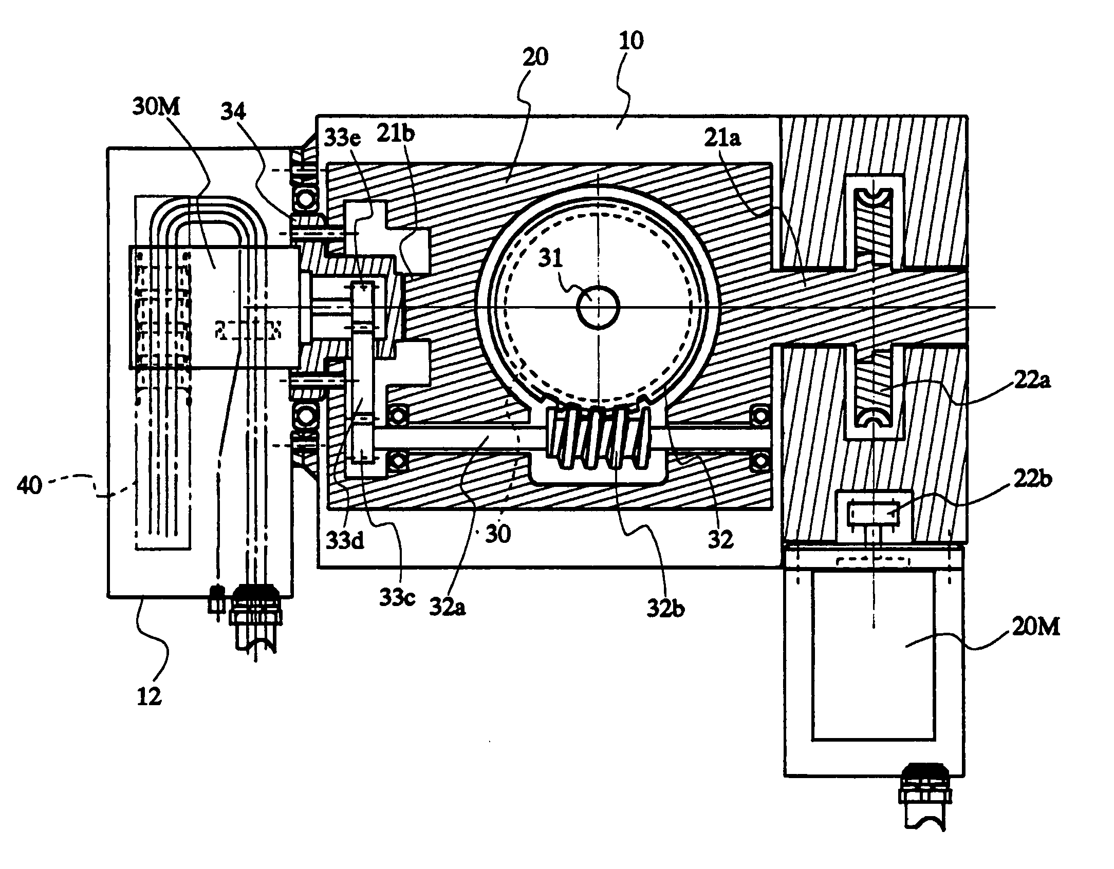
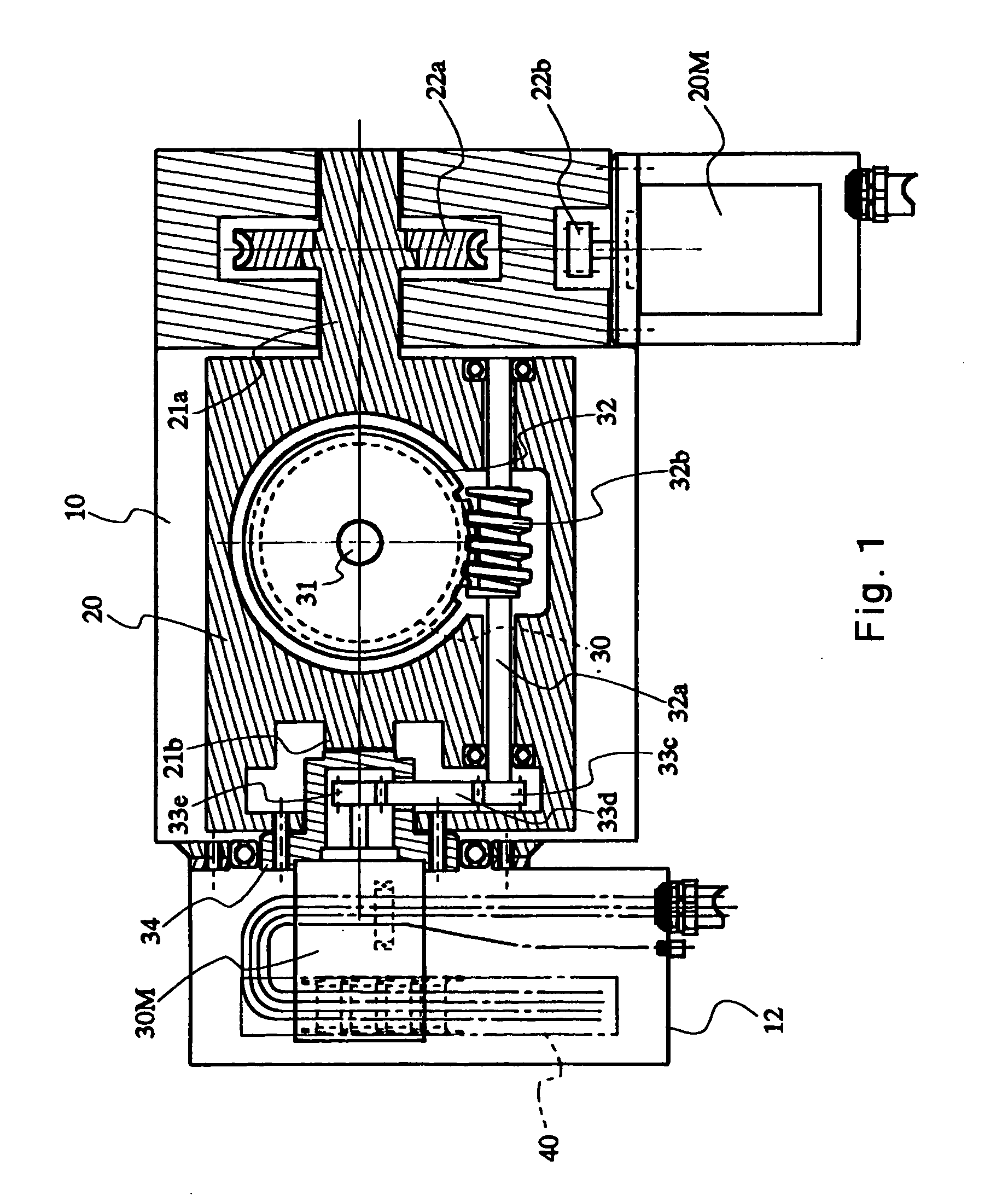
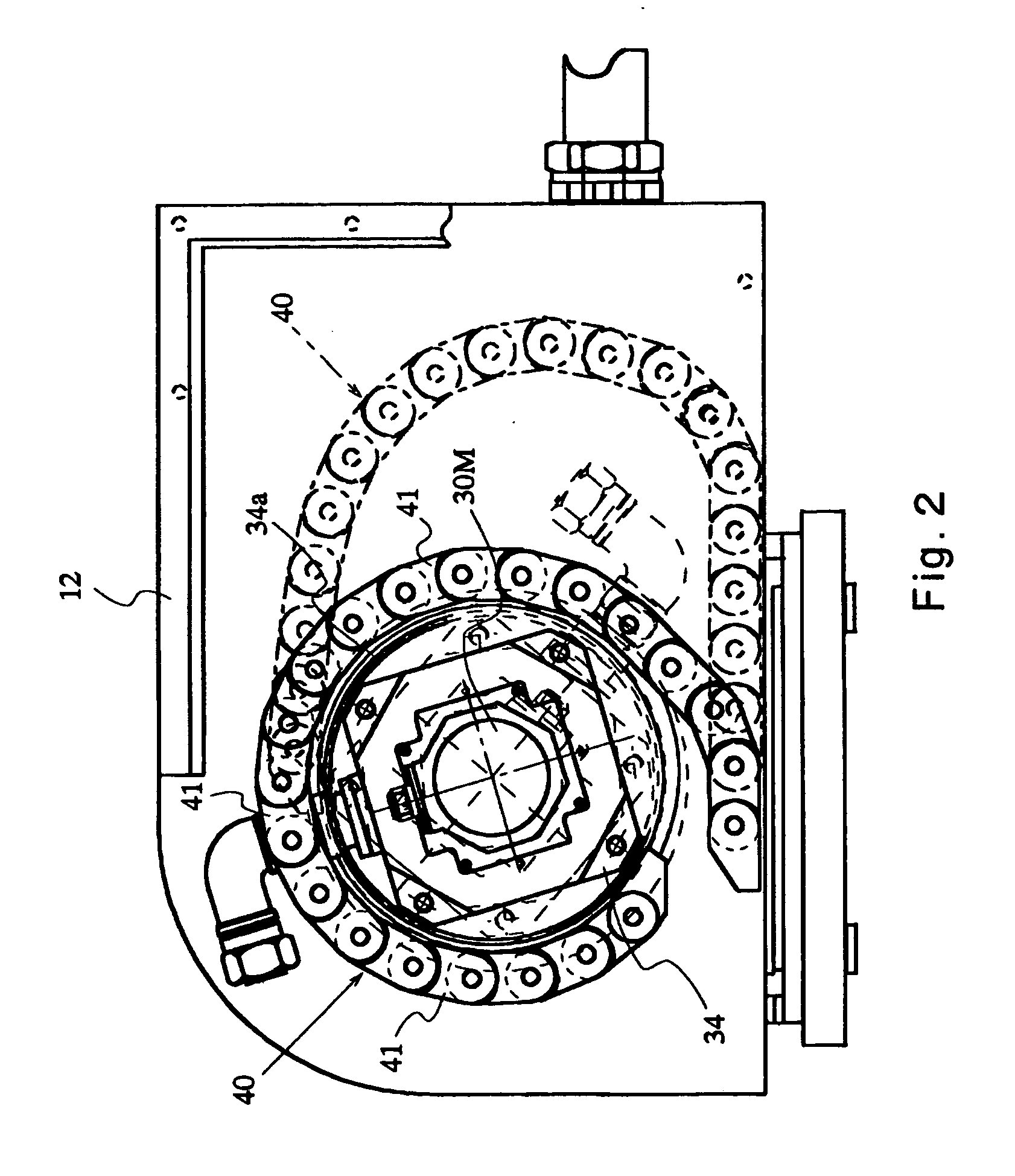
[0025]FIGS. 1 and 2 illustrate an embodiment of the present invention. Referring to FIG. 1, a tiltable-rotatable circular-table device mainly includes a main frame 10; a tiltable table 20; a circular table 30; a tilt-driving motor 20M; and a rotary-driving motor 30M.

[0026] The tiltable table 20 is provided with tiltable shafts 21a and 21b protruding from opposite sides of the tiltable table 20. The tiltable table 20 is rotatably supported by the main frame 10 with, for example, shaft bearings via the tiltable shafts 21a and 21b. Furthermore, the tiltable shaft 21a is provided with a worm wheel 22a, which is a part of a first drive-transmission mechanism for transmitting a driving force of the tilt-driving motor 20M to the tiltable table 20.

[0027] The tilt-driving motor 20M is securely disposed in the main frame 10. A gear 22b is fixed to an output shaft of the tilt-driving motor 20M. ...


PUM


Abstract

A tiltable-rotatable circular-table device for a machine tool includes a rotary-driving motor which is fixed to a tiltable table and is for rotating a circular table disposed above the tiltable table; a motor cover which is fixed to the main frame and is for housing the rotary-driving motor; and cables connected with the rotary-driving motor. The tiltable-rotatable circular-table device further includes a cable guide whose one end is fixed to the motor cover and the other end is fixed on a periphery of the rotary-driving motor. The cable guide is housed in the motor cover and is capable of surrounding at least a portion of the periphery of the rotary-driving motor so as to guide the cables in a direction in which the cables extend. The cable guide is bendable mainly in its thickness direction at multiple sections thereof such that the cable guide is capable of surrounding the rotary-driving motor.

Description

BACKGROUND OF THE INVENTION [0001] 1. Field of the Invention [0002] The present invention relates to tiltable-rotatable circular-table devices used as attachment devices for machine tools. In particular, the present invention relates to a tiltable-rotatable circular-table device including a main frame; a tiltable table having tilting shafts via which the tiltable table is axially supported on the main frame; a circular table rotatably disposed on the tiltable table; a tilt-driving motor which is disposed in the main frame and is provided for tilting the tiltable table via the tilting shafts; a rotary-driving motor which is fixed to the tiltable table and is provided for rotating the circular table; a motor cover which is fixed to the main frame and is provided for housing the rotary-driving motor; and cables connected with the rotary-driving motor. [0003] 2. Description of the Related Art [0004] In a typical tiltable-rotatable circular-table device, when a workpiece is loaded onto a...

Claims


Application Information

Patent Timeline
IPC IPC(8): B23Q1/00B23Q1/25B23Q1/54B23Q11/08B23Q16/02F16L3/015
CPCB23Q1/0009B23Q16/025B23Q11/08B23Q1/5437
Inventor OMORI, MITSURUOSAKI, HARUO
Owner TSUDAKOMA KOGYO KK
Why Eureka
Try Eureka