System and method for cable localization

a cable localization and system technology, applied in the field of system and a method for cable localization, can solve the problems of requiring additional hardware, unable to teach or suggest a mechanism, and unable to achieve low cost, efficient solutions.

Inactive Publication Date: 2005-09-29
CISCO TECH INC
View PDF10 Cites 73 Cited by
  • Summary
  • Abstract
  • Description
  • Claims
  • Application Information

AI Technical Summary

Benefits of technology

[0012] None of the background art solutions teaches or suggests a mechanism to determine the absolute physical location of a set-top box without requiring additional hardware. In addition, none of the background art solutions teaches or suggests a solution which is low cost, efficient and also enables the location to be determined through a mechanism that is at least partially external to the set-top box itself.
[0027] In addition, the system and method described in European Patent Application No. EP 0858184 enable the authorized user to record and playback or otherwise display the digital content, while preventing the user from producing and distributing multiple playable copies of the digital content to other, non-authorized users. Therefore, the authorized user is able to fully use and enjoy the digital content, while the content itself is still protected from unauthorized use.
[0028] The present invention, in certain preferred embodiments thereof, may optionally operate with the previously described background art systems as follows. An EMM (entitlement message) may need to be sent to subscribers, for example for targeted advertisement applications, in order for the set-top box to be able to use the correct ECM for decoding the content. A general broadcast of all EMM's to all set-top boxes would require too much bandwidth. It is therefore desirable to select EMM's for broadcast according to the cable topology. For example, EMM's may be transmitted according to the node alone or according to a group of nodes, or according to the hub. All of these components represent portions of the cable network, such that the EMM's only need to be sent to the relevant portion of the set-top boxes in the network and not to all set-top boxes. Thus, the ability of the present invention to determine the physical location of the set-top box may optionally be used to increase the efficiency of transmitting EMM's and / or other messages to the set-top boxes.

Problems solved by technology

None of the background art solutions teaches or suggests a mechanism to determine the absolute physical location of a set-top box without requiring additional hardware.
In addition, none of the background art solutions teaches or suggests a solution which is low cost, efficient and also enables the location to be determined through a mechanism that is at least partially external to the set-top box itself.

Method used


Image

  • System and method for cable localization
  • System and method for cable localization
  • System and method for cable localization

Examples


Embodiment Construction

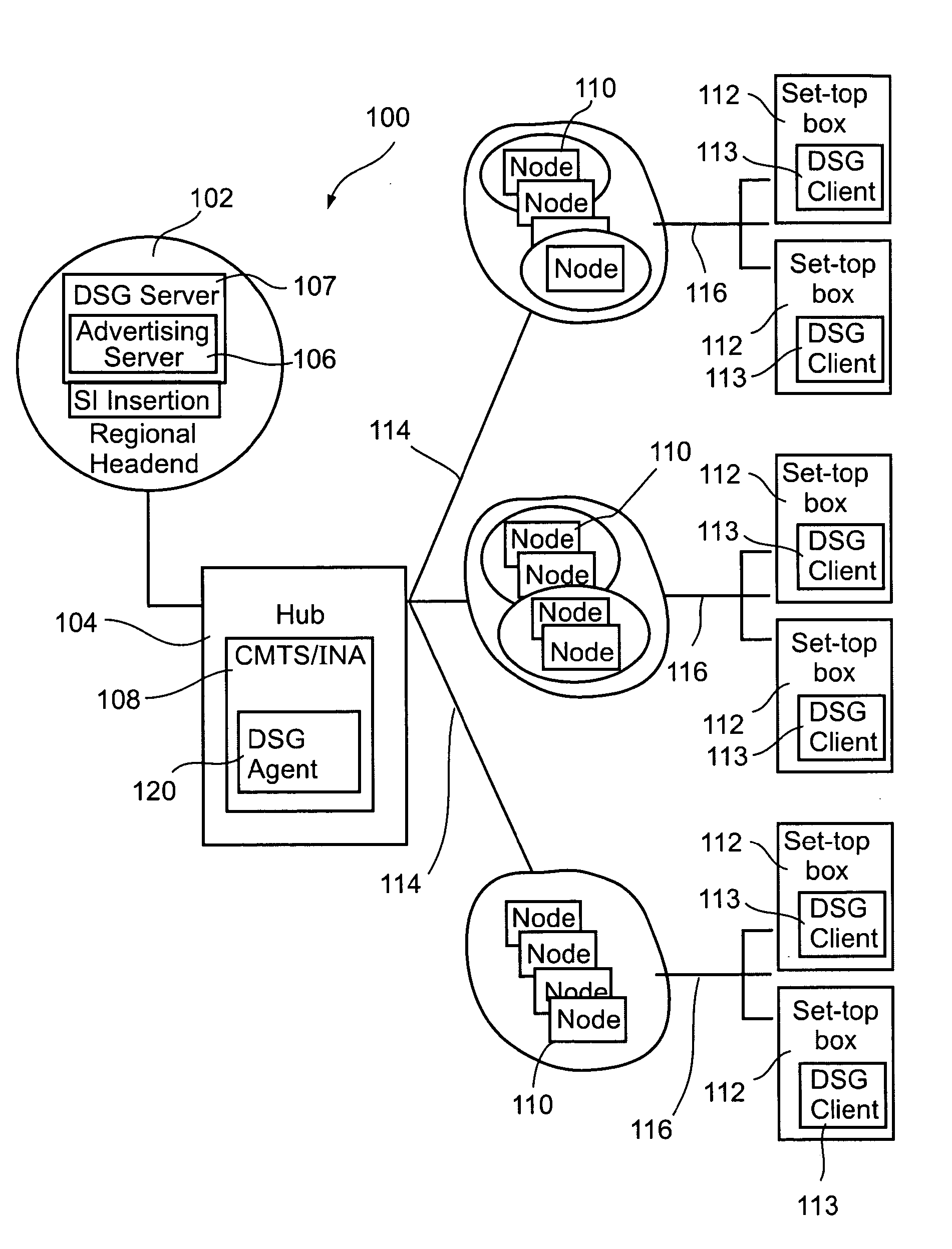
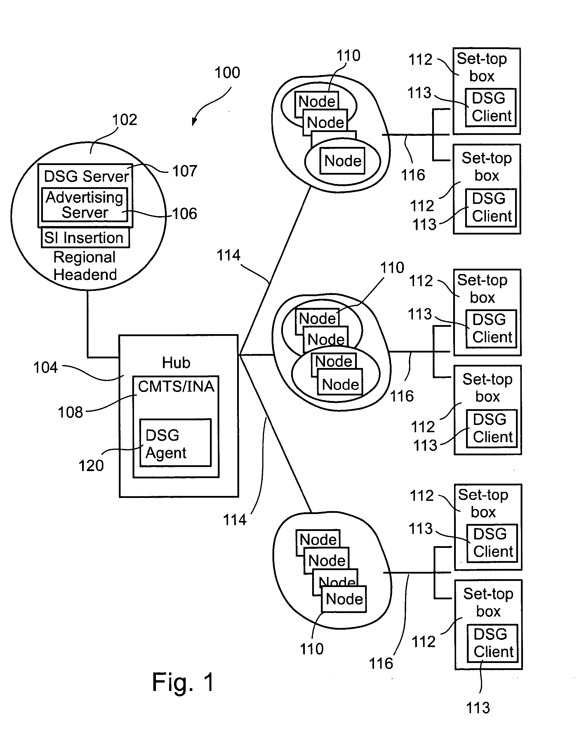
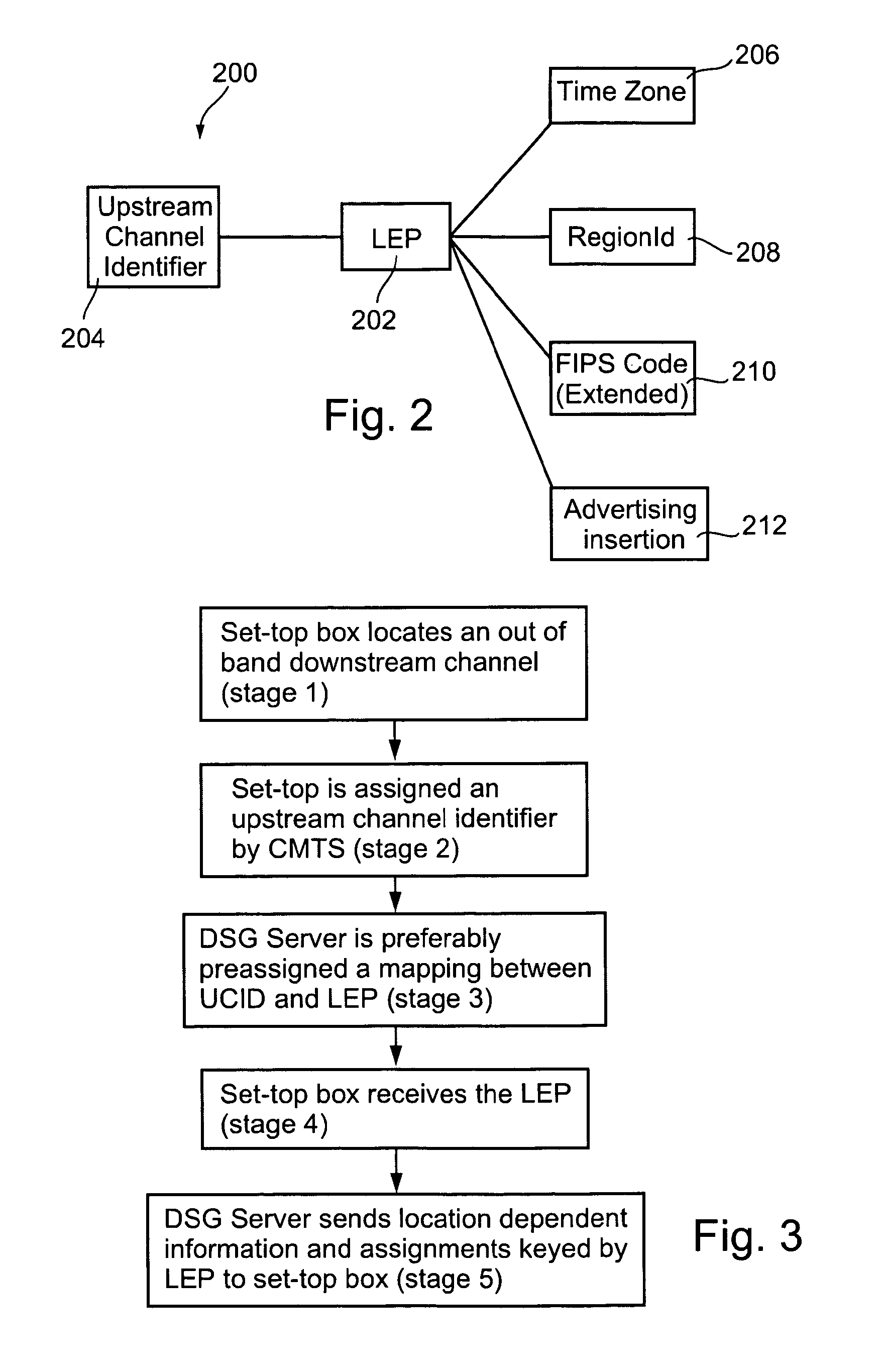
[0057] The present invention, in preferred embodiments thereof, is of a method and system for determining the physical location of individual set-top boxes, preferably at least partially by using existing information that is already passed within the system. The information is preferably external to the set-top boxes, which do not need to be preconfigured and / or configured with an internal or additional device (such as a smartcard for example). Rather, the information is passed during routine transmissions between the set-top box and the cable head-end. Thus, unlike other background art methods described previously, the present invention, in preferred embodiments thereof, does not require special information to be inserted into the content transport streams between the set-top box and the cable head-end, although OOB (out-of-band) message channels may optionally be used for message transmission. The present invention, in preferred embodiments thereof, is preferably implemented with ...


PUM


Abstract

A method and system for determining cable network topology for a plurality of set-top boxes connected to the cable network, the method comprising using existing information transmitted within the cable network for a non-location purpose to determine an absolute physical location of at least one set-top box within the topology. Related methods and apparatus are also described.

Description

FIELD OF THE INVENTION [0001] The present invention relates to a system and a method for cable localization. BACKGROUND OF THE INVENTION [0002] Many different types of content are currently distributed to users over a cable television system, in which a set-top box for a television set is typically physically connected to a cable network. The cable network connects these boxes to central head-ends, which transmit the content itself. Although this system requires that the cable be laid, usually underground, it is nonetheless a cost effective and efficient method to distribute content. In addition, such cable networks are now also used for broadband connections, which enable households to receive high bandwidth Internet connections. Such high bandwidth connections are becoming increasingly popular with consumers, thereby reinforcing the popularity of cable networks. [0003] However, in order for cable networks to operate efficiently, the physical location of the set-top box, relative t...

Claims


Application Information

Patent Timeline
Patent Type & Authority Applications(United States)
IPC IPC(8): G01R13/04G01R17/06H04H1/00H04H60/51H04L12/24H04N7/16
CPCH04H20/76H04H60/51H04N21/6547H04N7/165H04N21/25841H04L41/12H04L41/344
Inventor REVITAL, DANSHAPIRO, EDMONDVALENTINE, ANDREW
Owner CISCO TECH INC
Why Eureka
Try Eureka