Air-core coil and manufacturing method thereof

a technology of air-core coils and manufacturing methods, applied in the field of coils, can solve the problems of air-core coils with impaired frequency characteristics, rectangular or trapezoidal conductors with the problem of being more expensive than round conductors, and achieve the effects of reducing stray capacity, reducing manufacturing costs, and facilitating fabrication

Inactive Publication Date: 2005-09-29
SHT CO LTD
View PDF3 Cites 29 Cited by
  • Summary
  • Abstract
  • Description
  • Claims
  • Application Information

AI Technical Summary

Benefits of technology

[0010] With the air-core coil of the present invention, the plurality of unit turn portions providing each of the unit coil portions are lapped over in a direction intersecting the axis of the coil. These unit turn portions are sequentially formed by winding one continuous conductor. The winding numbers are consecutive, so that a stray capacity between turns is small. Furthermore, with each pair of unit coil portions adjacent to each other, a plurality of unit turn portions are lapped over axially of the coil. Each pair of the unit coil potions adjacent to each other is sequentially formed by the one continuous conductor, to render relatively small the stray capacity between turns.
[0012] According to the fabrication process, the partly finished air-core coil can be fabricated with ease by winding one conductor into a spiral form while varying the inner peripheral length, because with the partly finished air-core coil having arranged axially of the coil a plurality of unit turn portions which are different in inner peripheral length, the conductor forming the unit turn portions is not lapped over in a direction orthogonal to an axis of the coil (in a direction of winding diameter). The partly finished air-core coil thus obtained is merely compressed axially of the coil to thereby obtain the air-core coil of the present invention described.
[0014] According to the specific construction, the partly finished coil comprising a plurality of turn portions of varied inner peripheral lengths can be fabricated with ease by winding the conductor around the jig. Accordingly the fabrication process can be automated.
[0015] As described above, the air-core coil of the present invention exhibits a smaller stray capacity between the turns of the conductor than conventionally, resulting in reduced voltage between the layers, to obtain an excellent voltage resistance and improved frequency characteristics. Furthermore, the coil device including the air-core coil of the present invention can achieve high space factor irrespective of the type of conductor used. The air-core coil fabricating process of the present invention can be practiced automatically.

Problems solved by technology

This gives rise to the problem of the voltage resistance of the air-core coil 81.
Furthermore there is also the problem of impaired frequency characteristics of the air-core coil 81 due to the increased stray capacity.
However, the rectangular or trapezoidal conductor has the problem of being more expensive than the round conductor.
The conductor 9 is nevertheless difficult to wind around the core 7 automatically and must be wound by manual work, which involves the problem of low production efficiency.

Method used


Image

  • Air-core coil and manufacturing method thereof
  • Air-core coil and manufacturing method thereof
  • Air-core coil and manufacturing method thereof

Examples


Embodiment Construction

[0033] An embodiment of the present invention will be described below in detail with reference to the drawings.

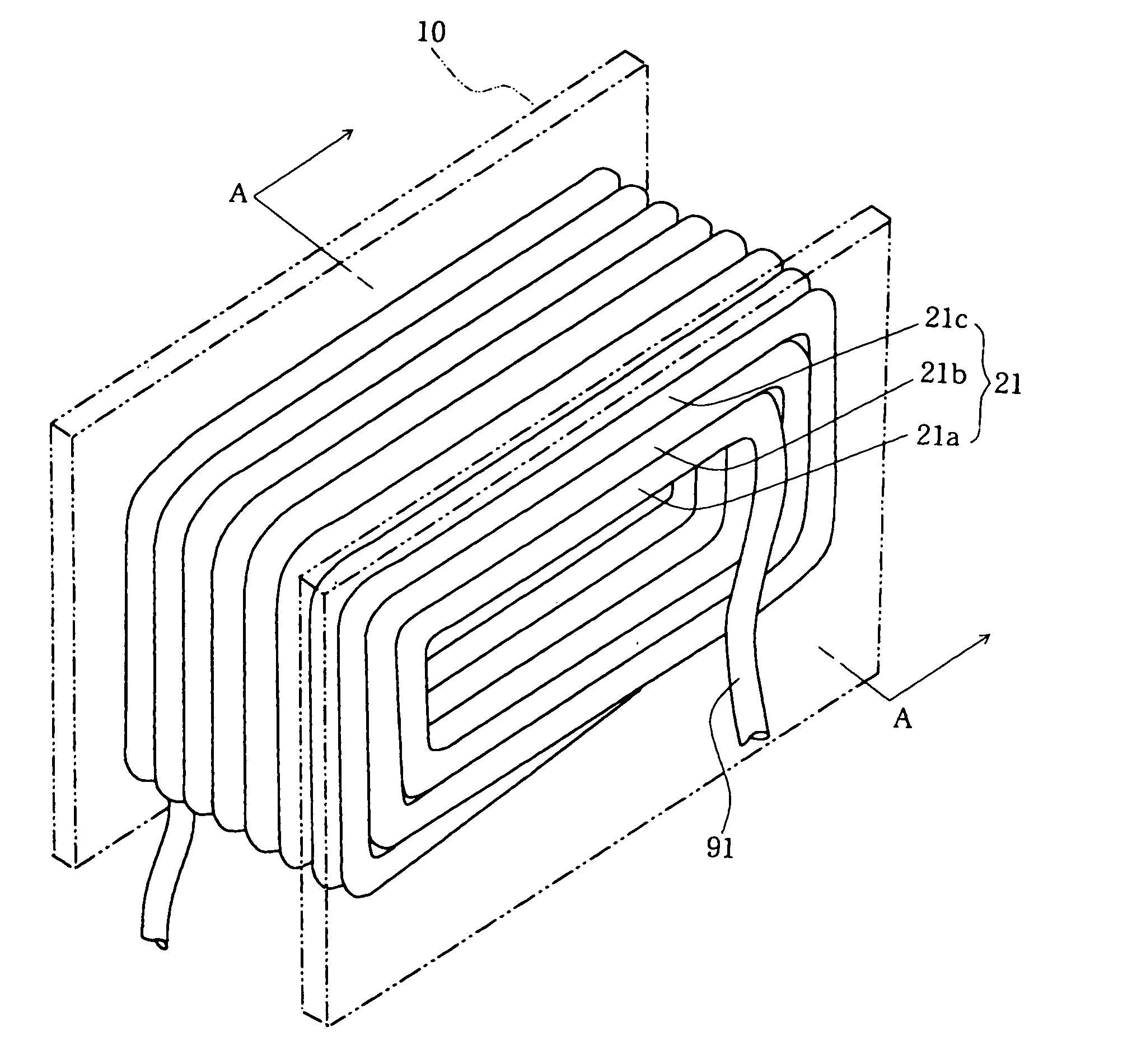
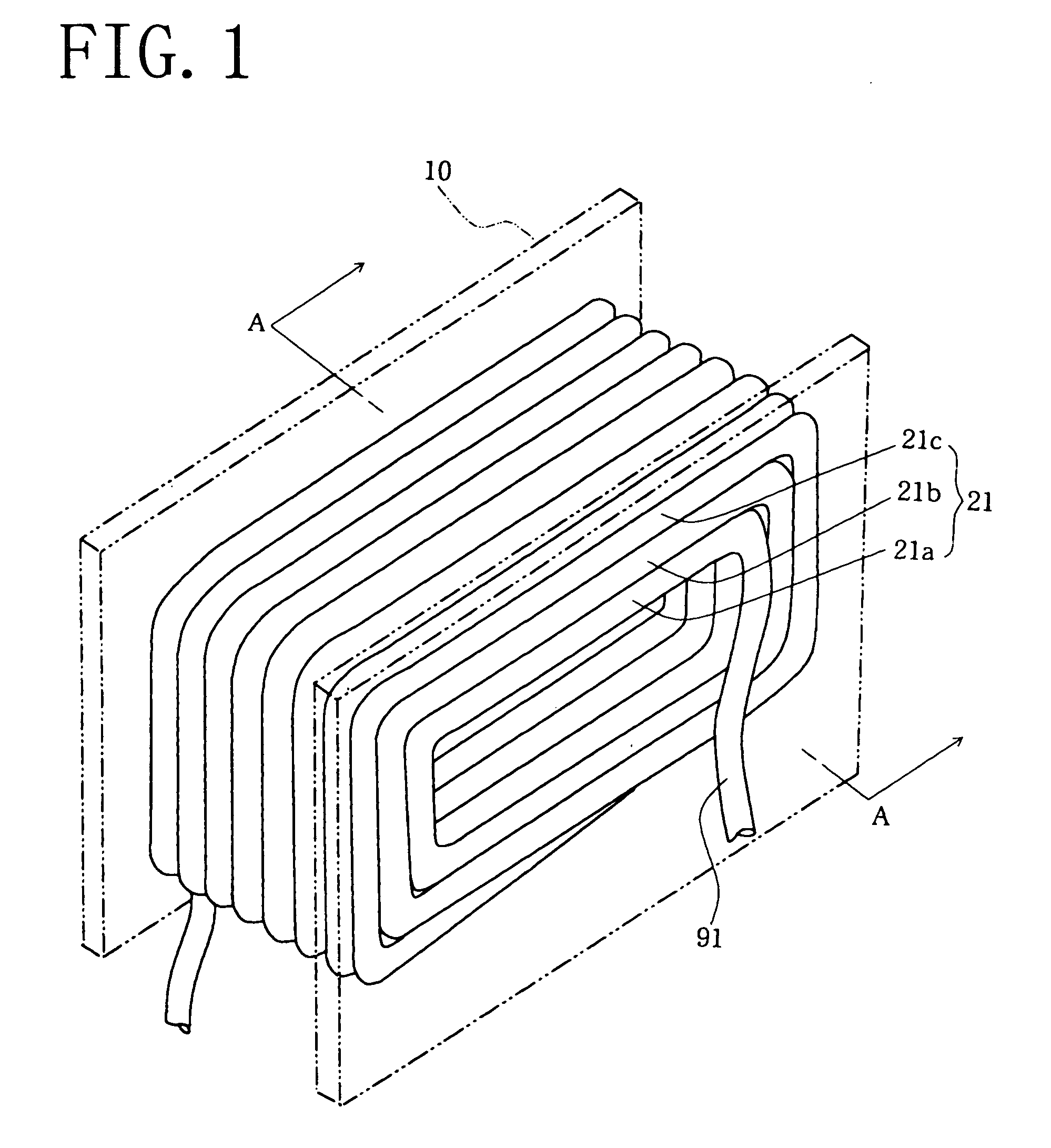
[0034]FIGS. 1 and 2 show the construction of an air-core coil 21 embodying the invention. The air-core coil 21 comprises a conductor 91 fitted around an outer surface of a bobbin 10, and has a layer-structure comprising a first layer 21a, second layer 21b and third layer 21c according to an example illustrated.

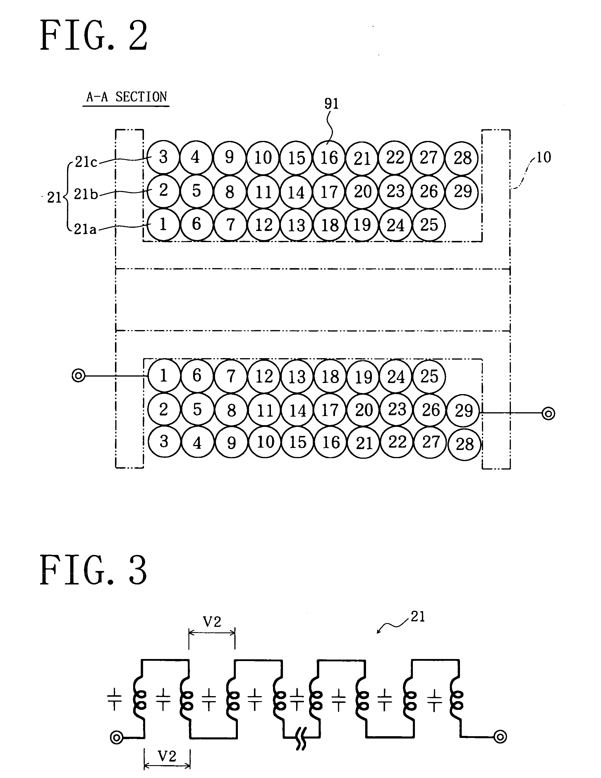
[0035] The air-core coil 21 is provided by winding one conductor therearound in the order indicated by the numerals 1 to 29 shown in FIG. 2. Unit coil portions are each provided by turns of consecutive numerals (1 to 3), (4 to 6), . . . , (25 to 27) and (28 to 29). The unit coil portions are arranged into ten rows axially of the coil.

[0036] Each of the unit coil portions comprises a unit turn portion having the greatest inner peripheral length, a unit turn portion having the medium inner peripheral length, and a unit turn portion having the smallest inner periphera...


PUM

PropertyMeasurementUnit
voltageaaaaaaaaaa
voltageaaaaaaaaaa
lengthaaaaaaaaaa

Abstract

The present invention provides an air-core coil 21 wherein one conductor is wound into a spiral form to thereby form consecutively, axially of the coil, a plurality of unit turn portions (25, 26, 27) which are different from each other in inner peripheral length and to form, axially of the coil, unit coil portions comprising the plurality of unit turn portions (25, 26, 27) to produce a partly finished coil 20, and thereafter the partly finished coil 20 is compressed to force the unit turn portion of small inner peripheral length inwardly of the unit turn portion of great inner peripheral length from among the unit turn portions providing each of the unit coil portions to thereby make each of the unit coil portions multi-layered. Thus the air-core coil 21 exhibits a smaller voltage across layers than conventionally and excellent frequency characteristics.

Description

TECHNICAL FIELD [0001] The present invention relates to coils to be provided in rectifier circuits, noise eliminating circuits, resonance circuits, etc. for use in various AC devices, and a process for fabricating the coils. BACKGROUND ART [0002] Conventionally known is a coil device of the troidal type, which comprises an air-core coil 81 fitted around a bobbin 10, as shown in FIG. 11. The air-core coil 81 is fabricated, for example, by winding a conductor around an outer surface of a wire winding jig (not shown) in the order indicated by the numerals of 1 to 29 as shown in the drawing. First the conductor is wound around the outer surface of the jig in the order of 1 to 10 to form a first layer 82, thereafter the conductor is wound around the outer surface of the first layer 82 in the order of 11 to 19 to form a second layer 83, and finally the conductor is wound around the outer surface of the second layer 83 in the order of 20 to 29 to form a third layer 84, to thereby fabricate...

Claims


Application Information

Patent Timeline
Patent Type & Authority Applications(United States)
IPC IPC(8): H01F5/02H01F27/28H01F27/34
CPCH01F5/02H01F27/34H01F27/2895H01F27/2823
Inventor YOSHIMORI, HITOSHI
Owner SHT CO LTD
Why Eureka
Try Eureka