
Ink ejection method and inkjet ejection device

Inactive Publication Date: 2005-09-29
BROTHER KOGYO KK
View PDF2 Cites 15 Cited by
  • Summary
  • Abstract
  • Description
  • Claims
  • Application Information

AI Technical Summary

Benefits of technology

[0007] The present invention is advantageous in that an inkjet head which is capable of suppress occurrence of satellite droplets and manufactured at a lower cost in comparison with a conventional inkjet head configured to suppress the satellite droplet.
[0016] Furthermore, the drive pulse signal selected, in the first condition, for the succeeding ink ejection cycle may include a cancel pulse that reduces a change of pressure of the corresponding pressure chamber.

Problems solved by technology

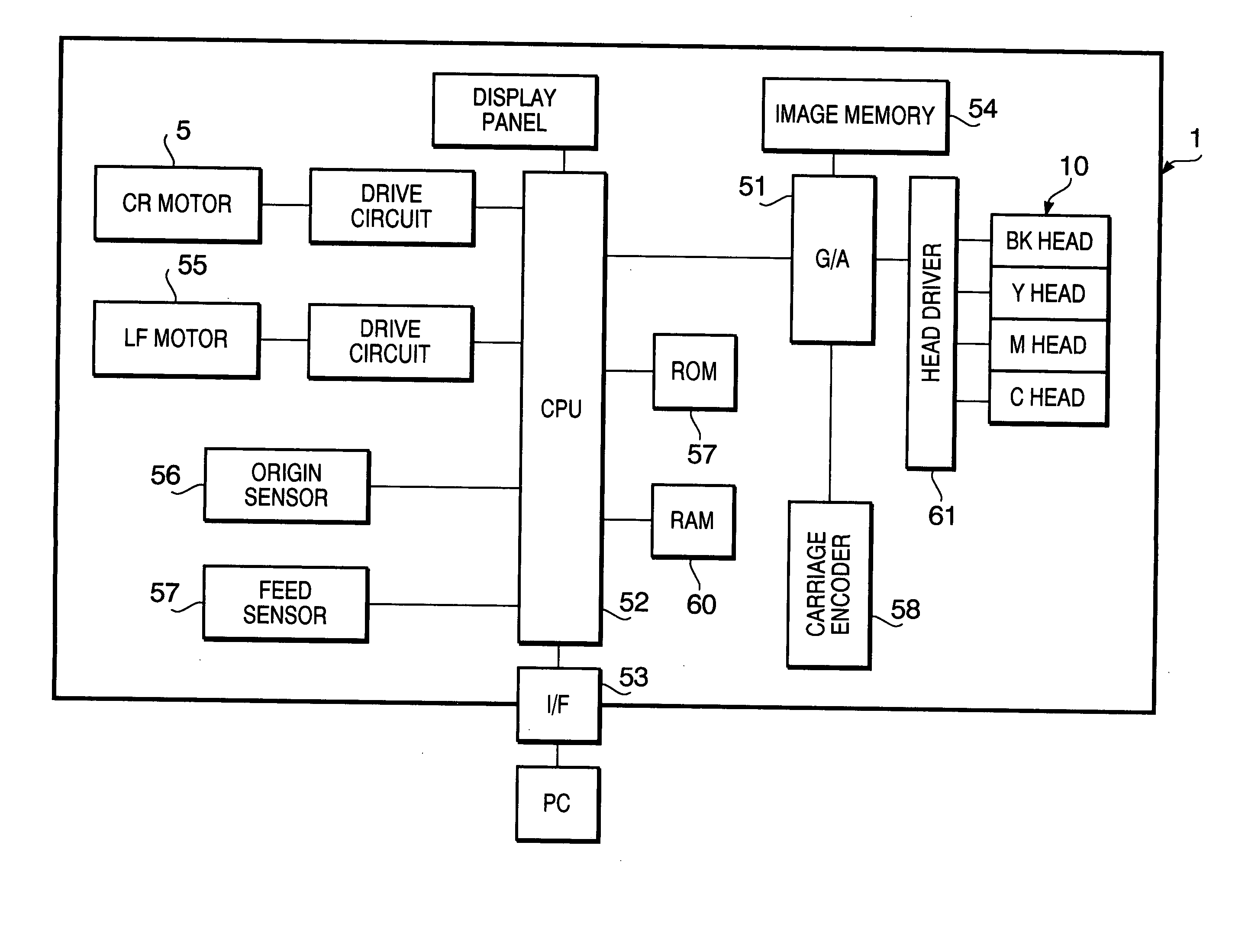
According to the configuration disclose in above U.S. Pat. No. 6,663,208 B2, in order to drive the inkjet head, a relatively complicated wave generating circuit is required.
Therefore, the pulse generating circuit for generating a signal having such a waveform is complicated.
Therefore, a relatively large storage capacity is required.
In view of the above, according to the conventional configuration, a manufacturing cost of the inkjet head may increase.

Method used


Image

  • Ink ejection method and inkjet ejection device
  • Ink ejection method and inkjet ejection device
  • Ink ejection method and inkjet ejection device

Examples


Embodiment Construction

[0030] Referring now to the accompanying drawings, an inkjet printer according to an exemplary embodiment of the invention will be described in detail.

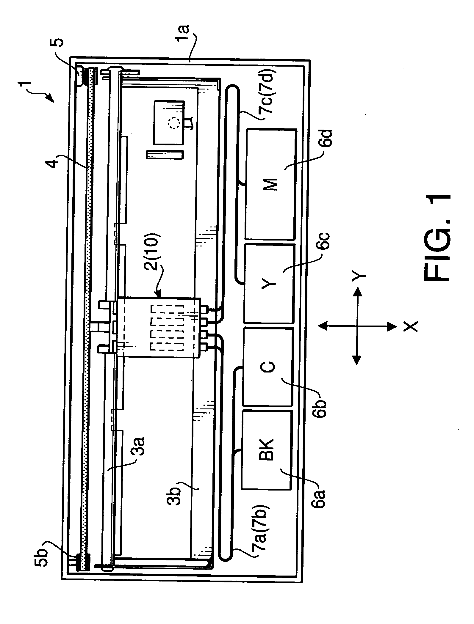
[0031]FIG. 1 schematically shows a plan view of an inkjet printer 1 according to the embodiment of the invention. The inkjet printer 1 is provided with a carriage 2 mounting a recording head 10, which is an inkjet head, on its lower surface. The carriage 10 is slidably supported by a pair guide rails 3a and 3b which are parallelly arranged inside a casing 1a of the inkjet printer 1. A timing belt 4 is provided in parallel with the guide rails 3a and 3b. The timing belt 4 is an endless belt wound around a driving shaft of a carriage motor 5 provided on a right-hand side of the casing 1a in FIG. 1, and a pulley 5b provided on a left-hand side of the casing 1a in FIG. 1. The carriage 2 is connected to the timing belt 4. As the carriage motor 5 is driven to rotate, the timing belt 4 moves in the direction parallel with the guide rails 3a...


PUM


Abstract

An ink ejecting device includes a plurality of nozzles, a plurality of pressure chambers respectively corresponding to the plurality of nozzles, an actuator capable of changing capacity of each of the plurality of pressure chambers. A first drive pulse signal is selected in accordance with dot information indicating dots to be formed on a recording medium successively. When the dot information for the current ejection cycle and the dot information for the succeeding ejection cycle indicate a first condition where ejection of a large amount of ink drop and no ejection of an ink drop, respectively, driving pulse signals for the current ejection cycle and the succeeding ejection cycle are selected, respectively. The driving pulse signals for the current ejection cycle and the succeeding ejection cycle are then output in the current ejection cycle and within the succeeding ejection cycle, respectively.

Description

INCORPORATION BY REFERENCE [0001] This application claims priority from Japanese Patent Application No. 2004-094631, filed on Mar. 29, 2004, the entire subject matters of the applications are incorporated herein by reference thereto. BACKGROUND OF THE INVENTION [0002] The present invention relates to an ink ejection method and an ink ejection device employing the ink ejection method. [0003] In the inkjet printer, an extra ink droplet called a satellite droplet may be generated in addition to a main ink droplet. When a plurality of droplets are continuously ejected to form a dot, and thereafter, if the pressure wave vibration in a pressure chamber is not reduced sufficiently, such a residual pressure wave vibration will cause an extra ink droplet to be ejected in the form of a satellite. Further, although the satellite ink droplet is not generated, formation of a succeeding ink dot may become unstable due to the variation of the pressure wave in the pressure chamber. Conventionally, ...

Claims


Application Information

Patent Timeline
IPC IPC(8): B41J2/045B41J2/01B41J2/055B41J2/14B41J2/205B41J29/38
CPCB41J2/04573B41J2/04581B41J2/04588B41J2/04593B41J2002/14419B41J29/38B41J2002/14217B41J2002/14225B41J2002/14306B41J2/14209
Inventor IRIGUCHI, AKIRA
Owner BROTHER KOGYO KK
Learn More