Monitoring system and setting method for the same

Inactive Publication Date: 2005-09-29
CANON KK
View PDF5 Cites 52 Cited by
  • Summary
  • Abstract
  • Description
  • Claims
  • Application Information

AI Technical Summary

Benefits of technology

[0006] The present invention has been made in order to solve the problem described above and has an object to provi

Problems solved by technology

With the conventional technique described above, however, a client connected to the camera server through a network is arranged at a place remote from the camera server, so when multiple parameters of a tracking function of the camera are set, it is difficult to know the d

Method used


Image

  • Monitoring system and setting method for the same
  • Monitoring system and setting method for the same
  • Monitoring system and setting method for the same

Examples


Example

[0033] Hereinafter, an embodiment of the present invention will be described.

[0034] In this embodiment of the present invention, a monitoring system is formed by a camera server and a setting client for an administrator (user). More specifically, in this embodiment, when a setting concerning a tracking function executed at the camera server is made at the setting client, progress or a final result of a tracking process of the camera server is sent to the setting client through a network and a resetting process is performed at the setting client based on the sent information.

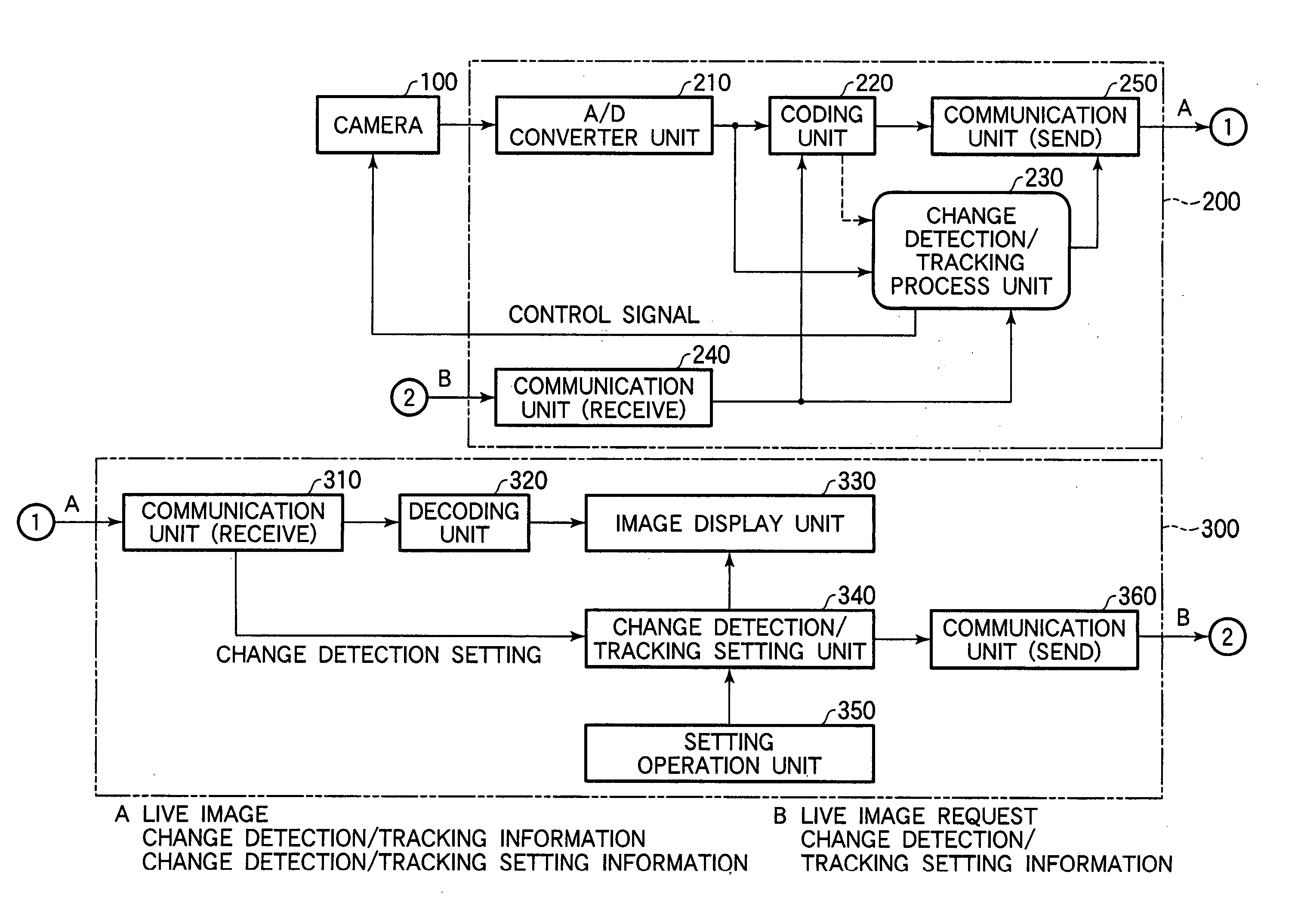
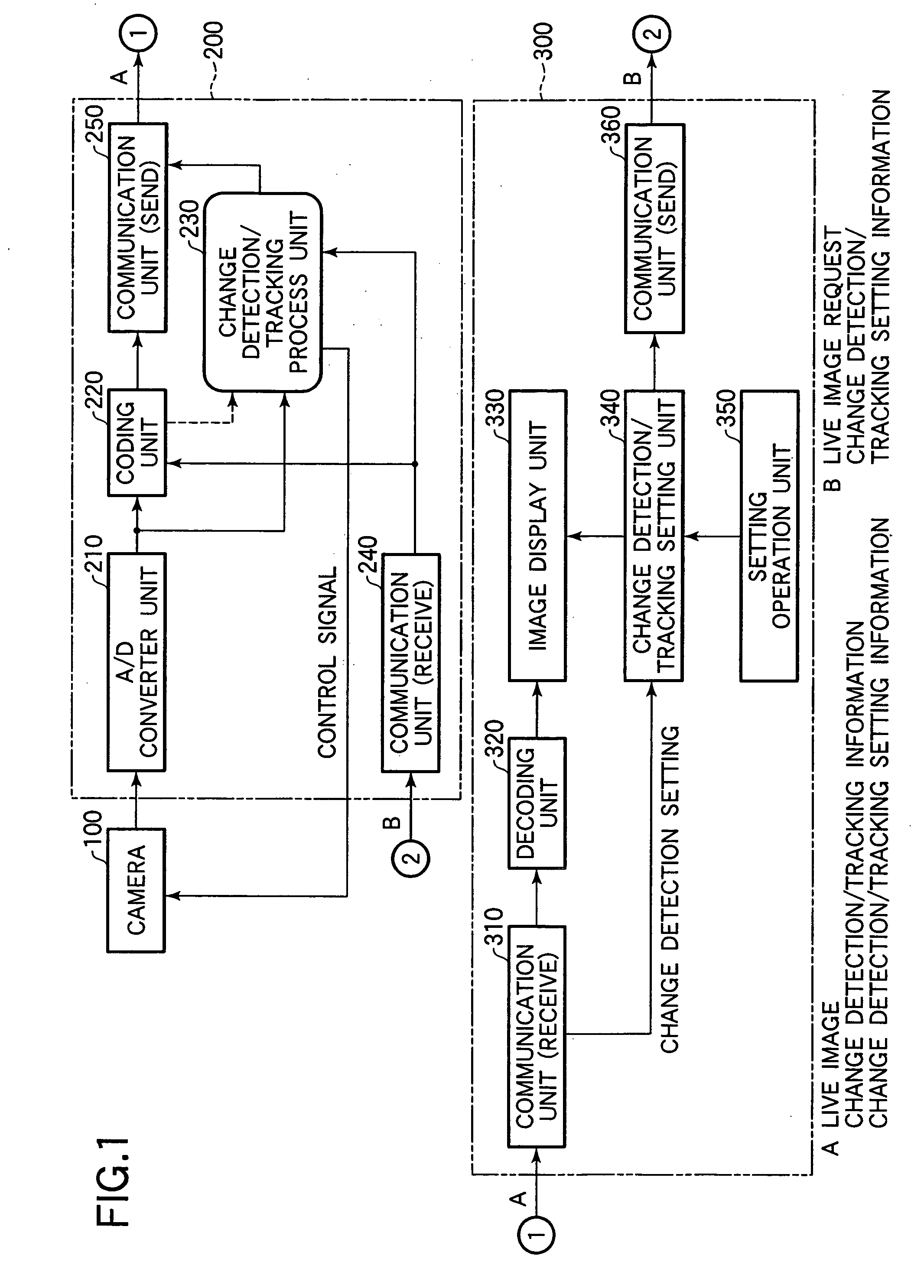
[0035]FIG. 1 is a block diagram showing an example of a construction of a monitoring system according to this embodiment.

[0036] In FIG. 1, the monitoring system includes a camera 100, a camera server 200, and a setting client 300. The camera server 200 includes an A / D converter unit 210, a coding unit 220, a change detection / tracking process unit 230, a communication unit (receive) 240, and a communication uni...


PUM


Abstract

In order to facilitate a setting of multiple parameters of a tracking function of a camera, in a setting window, an image display window is displayed in which a picked-up image sent from a camera server and an indicator indicating a change detection maximum area as a detection result of an image change detection process by the camera server are superimposingly on the picked-up image. In addition, in the setting window, a window is displayed in which a setting window is displayed which is used to make a setting of a tracking method by referring to an image displayed in the image display window.

Description

BACKGROUND OF THE INVENTION [0001] 1. Field of the Invention [0002] The present invention relates to a monitoring system, which uses a camera having a photographing object tracking function, and to a setting method for the monitoring system. [0003] 2. Related Background Art [0004] In recent years, a video image distribution system, in which a video image taken by a camera is distributed through a network and a monitoring system, in which an indoor or outdoor predetermined monitoring zone is monitored using a camera are becoming widespread. In addition, a network camera having a server function connectable to a network and a set-top box for connecting the camera to the network are commercialized. Such the network camera is generally referred to as the “camera server”, and there is known a camera server having a function of detecting a change of an image (resulting from a situation where, for instance, a suspicious person has entered into a predetermined monitoring zone) and activatin...

Claims


Application Information

Patent Timeline
IPC IPC(8): G06K9/00H04N7/18
CPCG06K9/00711G06V20/40
Inventor OYA, TAKASHIKAWAI, TOMOAKI
Owner CANON KK
Why Eureka
Try Eureka