Firearm Scope Method and Apparatus for Improving Firing Accuracy

a scope method and firing accuracy technology, applied in the field of firearms, can solve the problems of poor shot of a properly-calibrated firearm, insufficient account of firearm ballistics and ammunition, and widespread use of cameras in direct conjunction with firearms

Inactive Publication Date: 2005-09-29
GORDON TERRY J
View PDF31 Cites 54 Cited by
  • Summary
  • Abstract
  • Description
  • Claims
  • Application Information

AI Technical Summary

Benefits of technology

[0026] Also disclosed is a firearm scope for use in connection with a firearm, and a related method, comprising: a viewing monitor for displaying in real time, target images captured by a digital imaging array for capturing photographic images of a target; and the viewing monitor situated in relation to the firearm scope,

Problems solved by technology

Traditionally, however, the use of a camera in direct conjunction with a firearm was not widely practiced.
For example, the photographic record might establish that the scope was not aimed directly at the target, and that the ammunition struck precisely where the scope was inaccurately-aimed, indicating a poor shot of a properly-calibrated firearm.
This would indicate that the scope was misaligned with the barrel, that environmental conditions were a factor, that distance or inclination to the target was not properly taken into account and that the scope should actually have been aimed further above or below the target, or that the ballistics of the firearm and ammunition was not properly accounted for.
More to the point, a number of accuracy-affecting factors must be accounted for to achieve highly-accurate firing, and if they are not, the shot which is fired will not be as accurate as it can or should b

Method used


Image

  • Firearm Scope Method and Apparatus for Improving Firing Accuracy
  • Firearm Scope Method and Apparatus for Improving Firing Accuracy
  • Firearm Scope Method and Apparatus for Improving Firing Accuracy

Examples


Embodiment Construction

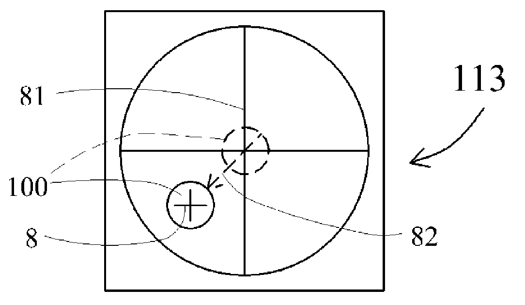
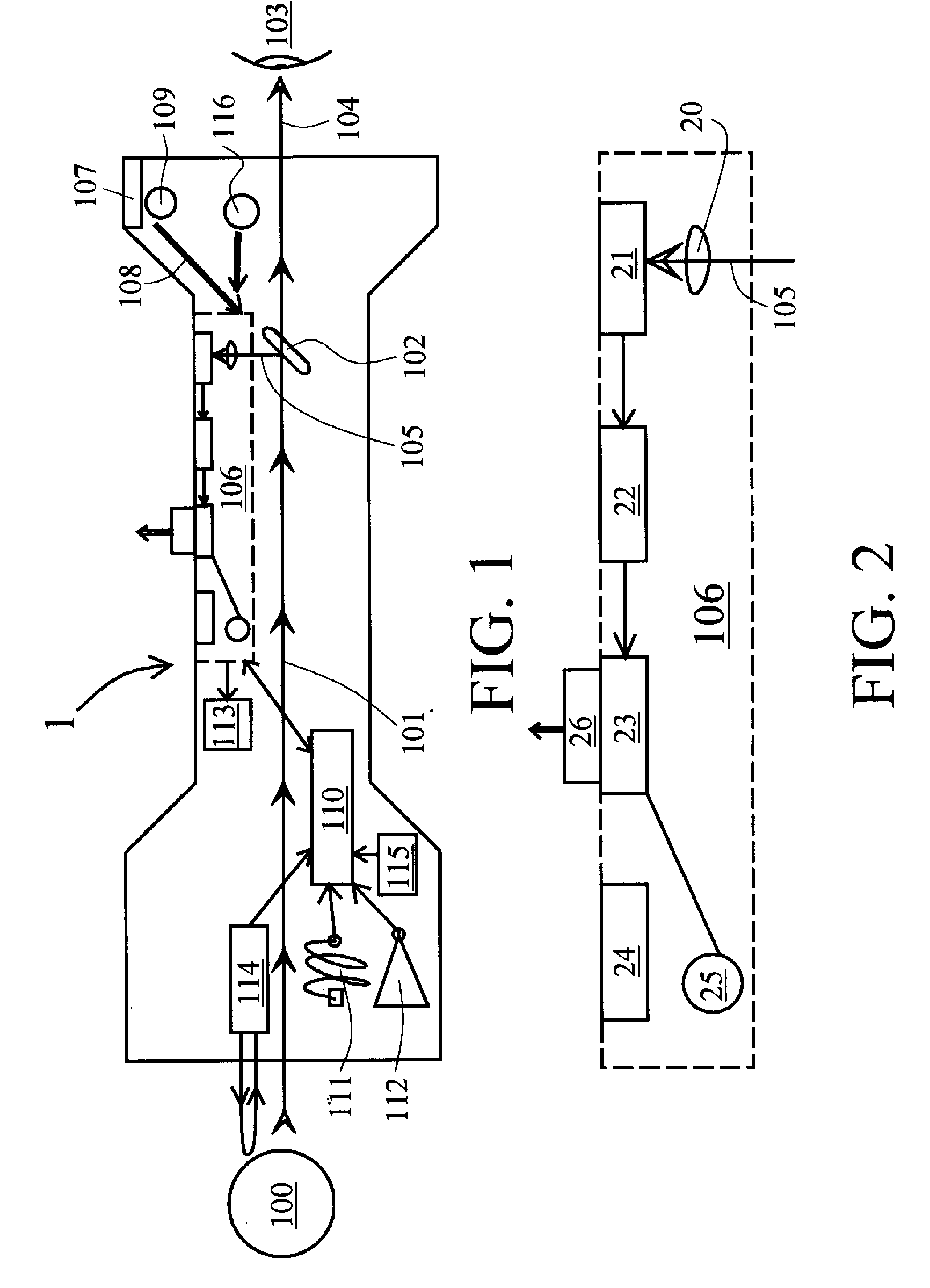
[0034]FIG. 7 is based on both FIGS. 1 and 4 insofar as it illustrates a rifle scope 1 through which the shooter can view the target image 100 as in FIG. 1, and insofar as, similarly to FIG. 4, viewing target image 100 directly through a lens is eliminated (or supplemented) in favor of viewing target image 100 on viewing monitor 113, see also FIG. 8.

[0035] Particularly, viewing monitor 113 schematically illustrated in FIGS. 1 and 4 is, in FIG. 7, situated upon photographic firearm apparatus 1 in a location such that it is viewable by a person firing the firearm when firing the firearm. Viewing monitor 113 receives image data from digital photography means 106, such that the actual image striking digital imaging array 21 (see also the enlargement of digital photography means 106 in FIG. 5) is displayed on viewing monitor 113 in real time. That is, viewing monitor 113 displays in real time, the target images captured by digital imaging array 21. As such, viewing monitor 113 can replac...


PUM


Abstract

A firearm scope and related method is disclosed, comprising: a movable aiming icon viewed juxtaposed with images of a target, automatically movable in relation to the images of the target based on at least one accuracy-affecting factor; whereby: the movable aiming icon can be used to aim the firearm at the target while accounting for the at least one accuracy-affecting factor. Additionally, a firearm scope and related method is disclosed, comprising: a viewing monitor for displaying in real time, target images captured by a digital imaging array for capturing photographic images of a target; and the viewing monitor situated in relation to the firearm scope, wherein the target images displayed thereon are viewable by a person firing the firearm when firing the firearm; whereby: the target images displayed on the viewing monitor can be used to aim the firearm at the target without parallax misalignment due to variation in positioning of an eye of the person firing the firearm.

Description

CROSS-REFERENCE TO RELATED APPLICATIONS [0001] This application is a continuation-in-part of pending U.S. application Ser. No. 10 / 711,267 filed Sep. 7, 2004, which in turn is a continuation of U.S. application Ser. No. 10 / 250,148 filed Jun. 6, 2003, now U.S. Pat. No. 6,792,206 issued Sep. 14, 2004; which in turn is a continuation of U.S. application Ser. No. 10 / 063,033 filed Mar. 13, 2002, now U.S. Pat. No. 6,580,876 issued Jun. 17, 2003; which in turn is a continuation of U.S. application Ser. No. 09 / 537,325 filed Mar. 29, 2000, now U.S. Pat. No. 6,363,223 issued Mar. 26, 2002, all of which are hereby incorporated by reference.FIELD OF THE INVENTION [0002] This invention relates generally to firearms, and in particular to ways of improving accuracy when a firearm is aimed and fired. Background of the Invention [0003] Commonly-invented U.S. Pat. Nos. 6,000,163; 6,363,223; and 6,580,876; and patent application Ser. No. 10 / 250,148; all disclose a method and apparatus for recording pho...

Claims


Application Information

Patent Timeline
IPC IPC(8): F41G1/38F41G1/54G03B17/38G03B29/00
CPCF41A33/00F41C27/00F41G1/38H04N5/2252G03B17/00G03B29/00F41G1/54H04N23/51
Inventor GORDON, TERRY J.
Owner GORDON TERRY J
Why Eureka
Try Eureka