
Rotatable roller, image forming apparatus employing same, and image forming apparatus cartridge employing same

Active Publication Date: 2005-09-29
SHARP KK
View PDF4 Cites 0 Cited by
  • Summary
  • Abstract
  • Description
  • Claims
  • Application Information

AI Technical Summary

Benefits of technology

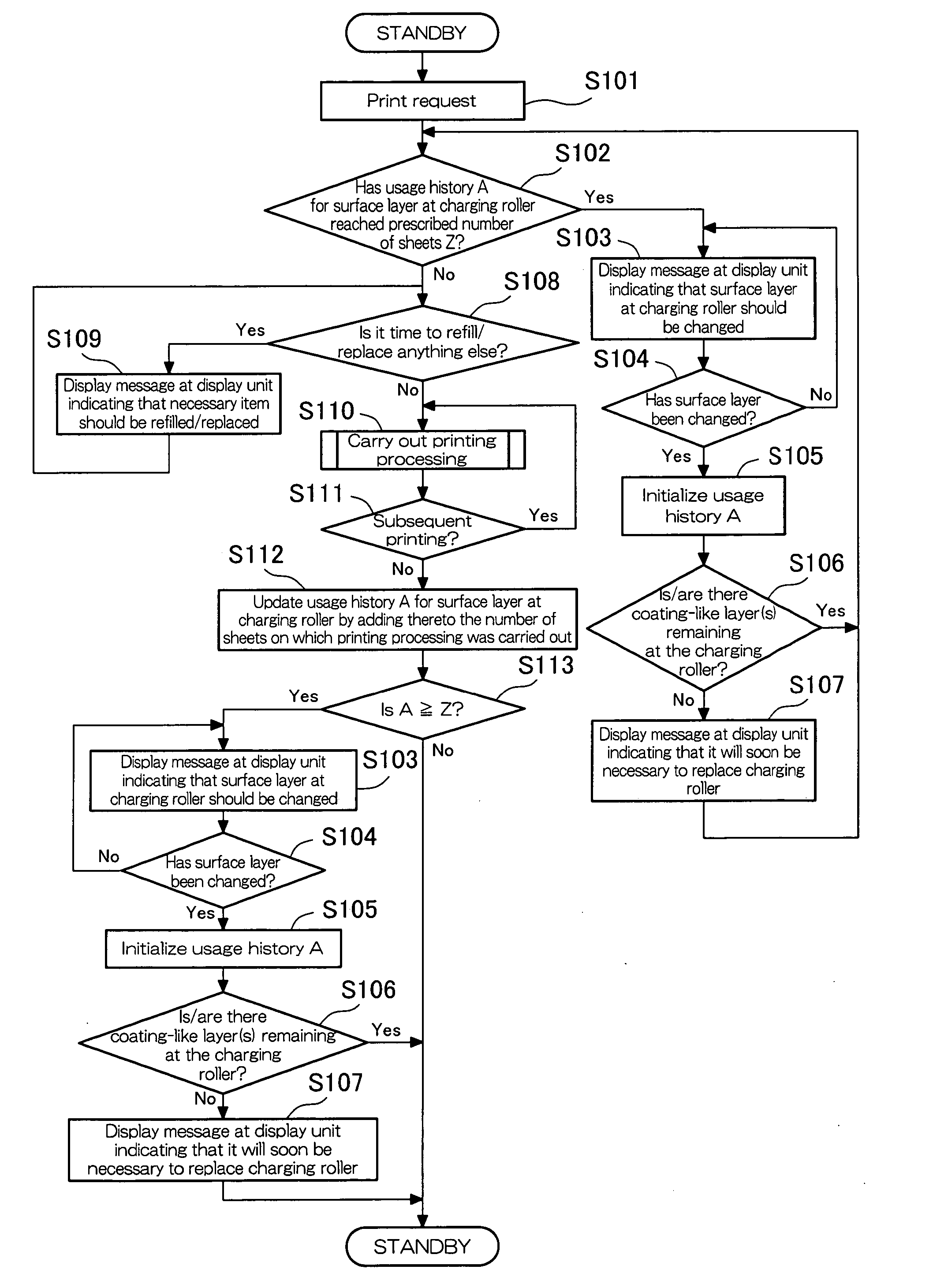
[0013] A rotatable roller in accordance with one or more embodiments of the present invention is such that there are a plurality of the coating-like layers sequentially strippably laminated at the outer circumferential surface thereof. This being the case, when outermost coating-like layer surface(s) of the rotatable roller become deteriorated, it will be possible, by stripping off such coating-like layer(s) therefrom, to reveal subsequent coating-like layer surface(s) and rejuvenate the rotatable roller surface(s). This will make it possible for electric potential(s) to be imparted in stable fashion to the electrostatic latent image carrier(s). Furthermore, because rejuvenation of surface(s) of the rotatable roller is facilitated, it is possible to minimize the damage incurred by the electrostatic latent image carrier surface(s).
[0046] Where this is the case, because the control means is / are provided, it is possible at appropriate time(s) to strip off the coating-like layer(s) and rejuvenate the rotatable roller surface(s). As a result, it is possible to minimize the damage incurred by the electrostatic latent image carrier surface(s), making it possible to increase longevity of the electrostatic latent image carrier(s).

Problems solved by technology

However, they have the disadvantage that they produce a large amount of ozone.
However, as there is a tendency for roller surface(s) to deteriorate, it will be necessary to periodically carry out replacement of roller(s).
However, with Patent Reference No. 1, because there is a gap between the electrically conductive tube and the electrically conductive elastic roller, when the electrically conductive tube and the electrically conductive elastic roller are made to rotate in idler fashion by the photosensitive body, the locus at which the electrically conductive elastic roller contacts the electrically conductive tube is always changing in unstable fashion.
This being the case, it is possible that resistance between the electrically conductive elastic roller and the photosensitive drum will be unstable, and that charging of the photosensitive drum by the electrically conductive elastic roller and the electrically conductive tube will also be unstable.
Accordingly, for stable charging of the photosensitive drum, there being no alternative but to employ a roller in which an electrically conductive film is in intimate contact with the roller surface, roller replacement has been unavoidable.
Furthermore, this sort of problem which has been described with respect to charging rollers has also been shared by charge removal rollers coming in contact with photosensitive drum(s) or the like and removing charge therefrom, cleaning rollers coming in contact with photosensitive drum(s) or the like and carrying out cleaning thereof, transfer rollers transferring development image(s) from photosensitive drum surface(s) to recording paper, and so forth, where it has also been necessary to carry out roller replacement in the event of deterioration of the roller surface.

Method used


Image

  • Rotatable roller, image forming apparatus employing same, and image forming apparatus cartridge employing same
  • Rotatable roller, image forming apparatus employing same, and image forming apparatus cartridge employing same
  • Rotatable roller, image forming apparatus employing same, and image forming apparatus cartridge employing same

Examples


first embodiment

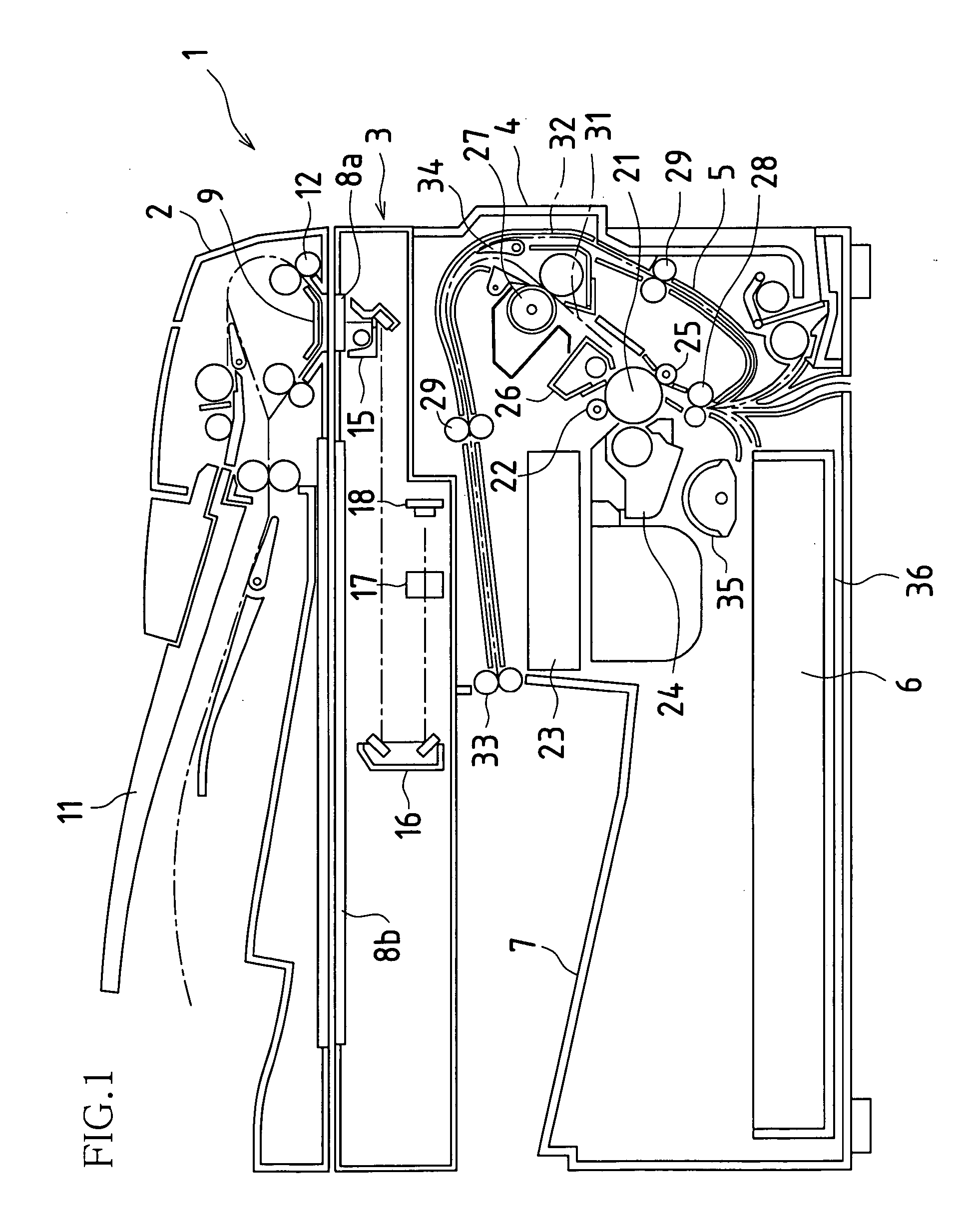
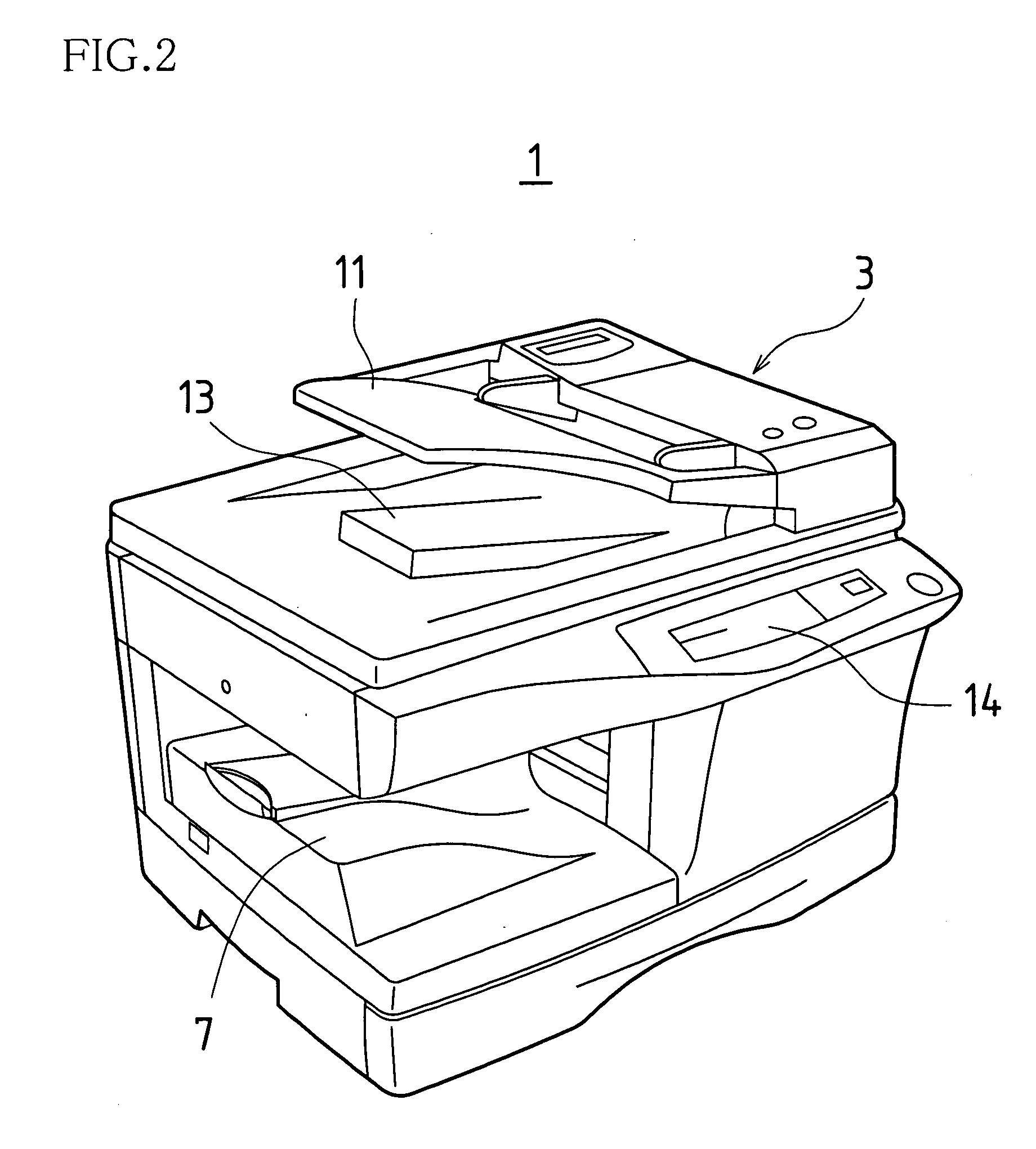
[0065]FIG. 1 is a side view showing a first embodiment of an image forming apparatus in accordance with the present invention. Furthermore, FIG. 2 is an oblique view showing the image forming apparatus of the present embodiment. This image forming apparatus 1 is capable of selective operation pursuant to copier mode in which original image(s) is / are captured and is / are printed on recording paper; facsimile mode in which original image(s) is / are captured and is / are transmitted, and / or in which original image(s) is / are received and is / are printed on recording paper; printer mode in which image(s) received via network(s) from information terminal apparatus(es) is / are printed on recording paper; and so forth. Describing its structure in broad terms, this image forming apparatus 1 comprises original transport unit or units 2, capturing unit or units 3, printing unit or units 4, recording paper transport unit or units 5, media supply unit or units 6, and media discharge unit or units 7.

[...


PUM


Abstract

As outermost coating-like layer(s) of charging roller(s) is or are made to contact and / or slide against photosensitive drum(s), charge is applied from the outermost coating-like layer(s) to the photosensitive drum(s), charging the photosensitive drum(s). This being the case, resistance of the outermost coating-like layer(s) of the charging roller(s) fluctuates, and surface(s) thereof become scratched and so forth, and gradually deteriorate. Moreover, if remedial action is not taken, charging capability of the charging roller(s) may decrease, leading to nonuniformity in charging of the photosensitive drum(s) and causing lowering of image quality and / or reduction in service life of the photosensitive drum(s). The outermost coating-like layer(s) of the charging roller(s) is or are therefore periodically stripped off therefrom to rejuvenate the charging roller surface(s).

Description

BACKGROUND OF INVENTION [0001] This application claims priority under 35 USC 119(a) to Patent Application No. 2004-95914 filed in Japan on 29 Mar. 2004, the content of which is hereby incorporated herein by reference in its entirety. [0002] The present invention pertains to rotatable roller(s) rotating with an outer circumferential surface(s) thereof contacting and / or sliding against at least one electrostatic latent image carrier(s), and pertains to image forming apparatus(es) employing same, and pertains to image forming apparatus cartridge(s) employing same. [0003] As is known, in electrophotographic image forming apparatuses, as a photosensitive drum (electrostatic latent image carrier) is made to rotate, a charging apparatus causes the surface of the photosensitive drum to become uniformly charged; a beam of light is scanned across the surface of the photosensitive drum, forming an electrostatic latent image on the photosensitive drum; developer is made to adhere to the electro...

Claims


Application Information

Patent Timeline
IPC IPC(8): G03G15/00G03G15/02G03G21/00G03G15/16
CPCG03G15/1685G03G15/0233
Inventor SHINKAWA, KOHJIISHII, HIROSHI
Owner SHARP KK
Learn More