
Fuser nip release mechanism

a technology of nip release mechanism and fuser, which is applied in the direction of electrographic process apparatus, optics, instruments, etc., can solve the problems of pc drum damage, media likely trapped, pc drum to be pulled off the front door, etc., to facilitate the service of the printing device, reduce potential roll or roll cover distortion, and simplify the loading structure

Active Publication Date: 2005-09-29
LEXMARK INT INC
View PDF8 Cites 5 Cited by
  • Summary
  • Abstract
  • Description
  • Claims
  • Application Information

AI Technical Summary

Benefits of technology

The present invention provides a printing apparatus with a fuser assembly and a cover assembly that can be opened and closed for service. The invention includes a nip release mechanism that automatically unloads the fuser nip when the cover is opened and automatically loads the fuser nip when the cover is closed. The invention simplifies the process of loading and unloading the fuser nip and reduces potential roll or roll cover distortion. The technical effects of the invention are improved serviceability and simplified operation of the printing device.

Problems solved by technology

As a result, if a paper jam or other process interruption occurs while a portion of the media is still in the fuser nip, the media is likely trapped in at least one and as many as four transfer nips.
The media is likely pulled out of the transfer nips rapidly as the door is opened, which could cause damage to the PC drums or even cause the PC drums to be pulled off the front door.
The paper will tug on the PC drum and slip in the transfer nips, possibly scratching the drums or even pulling them from their located features in the front door.
This requires an additional action by the user, and is not desirable.
Further, because the fuser load is high, significant mechanical advantage is required, which results in a large, unsightly fuser nip release lever.
Since opening the cover does not automatically release the fuser nip, it is possible that a user could open the cover and attempt to remove a jam without releasing the fuser nip lever potentially causing damage to the machine.
A disadvantage of this design is that the base machine applies considerable load to the fuser module, which makes inserting or removing the fuser module difficult for the user.
A disadvantage of this design is that the mechanism is expensive and may require a separate motor in the case of printers in which the fuser motor is dedicated to driving the fuser rolls forward and backward in a duplexing arrangement.

Method used


Image

  • Fuser nip release mechanism
  • Fuser nip release mechanism
  • Fuser nip release mechanism

Examples


Embodiment Construction

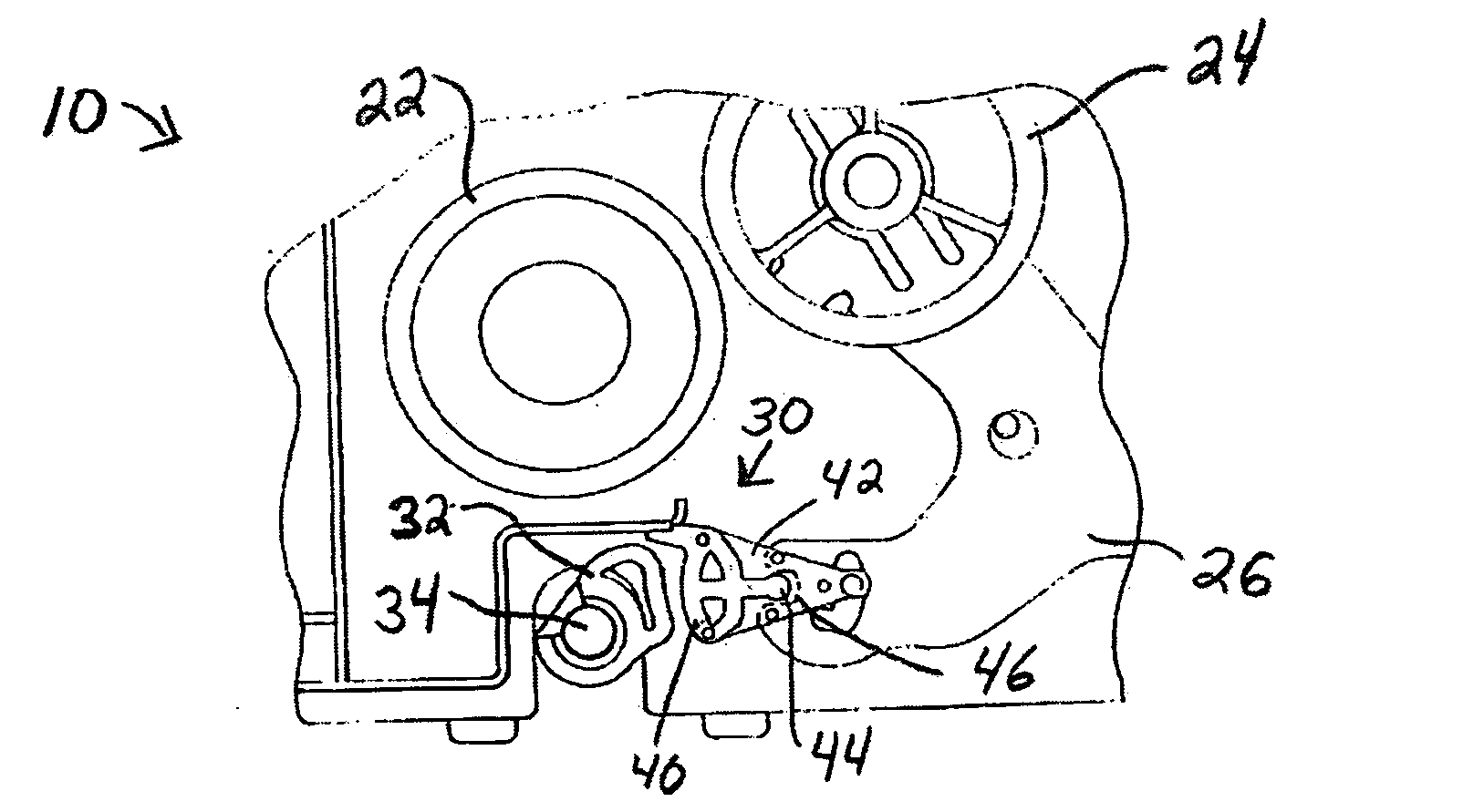
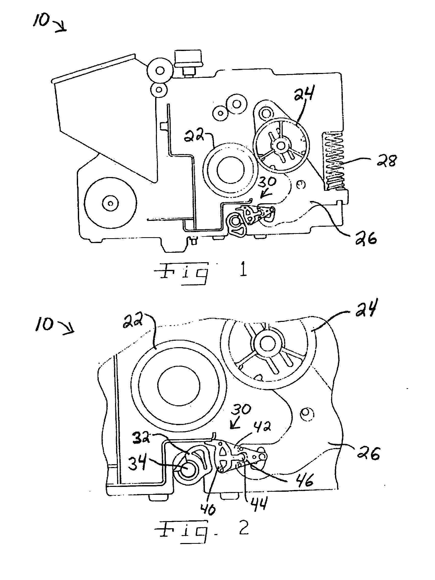
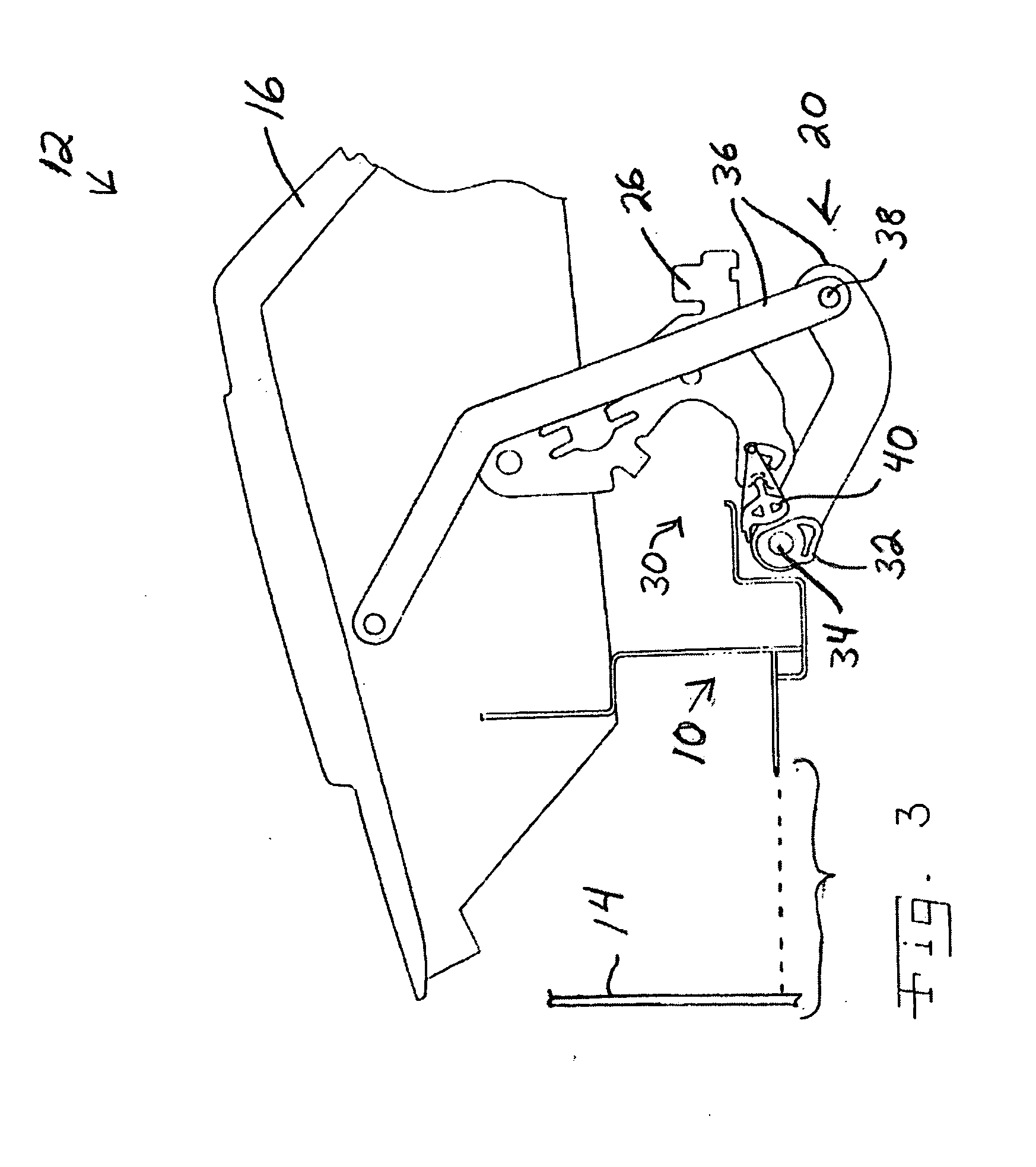
[0030] Referring now to the drawings and particularly to FIG. 1, there is shown an embodiment of a fuser module 10 in accordance with the present invention, suitable for use in an electrophotographic (E.P.) printing apparatus 12 shown in fragmentary form in FIGS. 3 and 4. Apparatus 12 further includes a machine frame 14, a fragment thereof which is schematically represented in FIG. 3. Fuser module 10 is removable from frame 14, as indicated by the dashed line in FIG. 3 interconnecting fuser module 10 and machine frame 14. A cover assembly 16 is pivotally connected to machine frame 14, and can be rotated between closed (FIG. 3) and opened (FIG. 4) positions. A linkage assembly 20 interconnects cover assembly 16 and components of fuser module 10, as will be described in further detail hereinafter. Apparatus 12 further includes other components of a print engine, media feed system and the like (not shown) which are well known to those skilled in the art and will not be described in fur...


PUM


Abstract

A nip release mechanism for a fuser of a printing device includes a movable component in the printer base frame moved by opening and closing a cover, and a follower component in the fuser which follows movement of the movable component to adjust positions of a fuser pressure roll.

Description

BACKGROUND OF THE INVENTION [0001] 1. Field of the Invention [0002] The present invention relates generally to fusers and electrophotographic printing devices, and, more particularly, to release mechanisms that unload the nip formed by the pressure roll against the hot roll in the fuser. [0003] 2. Description of the Related Art [0004] In the electrophotographic (EP) imaging process used in printers, copiers and the like, a photosensitive member, such as a photoconductive drum or belt, is uniformly charged over an outer surface. An electrostatic latent image is formed by selectively exposing the uniformly charged surface of the photosensitive member. Toner particles are applied to the electrostatic latent image, and thereafter the toner image is transferred to the media intended to receive the final permanent image. The toner image is fixed to the media by the application of heat and pressure in a fuser. [0005] A fuser is known to include a heated roll and a pressure roll, each cover...

Claims


Application Information

Patent Timeline
Patent Type & Authority Applications(United States)
IPC IPC(8): G03G15/20
CPCG03G15/2035
Inventor GOGATE, HRISHIKESH PRAMODPORTIG, HARALD
Owner LEXMARK INT INC
Learn More