Fitting member and manufacturing method thereof

a technology of fitting parts and manufacturing methods, applied in the direction of valve operating means/releasing devices, coupling device connections, mechanical devices, etc., can solve the problems of high cost, hydraulic oil may leak from the clearance, and it is difficult to control the dimensional accuracy of the base portion, etc., to achieve the effect of more elasticity

Inactive Publication Date: 2005-09-29
AISIN SEIKI KK
View PDF2 Cites 0 Cited by
  • Summary
  • Abstract
  • Description
  • Claims
  • Application Information

AI Technical Summary

Benefits of technology

[0011] According to an aspect of the present invention, a fitting member which forms, together with a fitted member, a fitting structure between a protruding portion and a hole portion, comprises a fitting member unit and a lubricating layer that covers the fitting member unit, wherein the lubricating layer includes a synthetic resin layer that has more elasticity than material used for the fitting member unit and inorganic particles that protrude from a surface of the synthetic resin layer.

Problems solved by technology

Thus, a cold forging needs to be preformed on several occasions and an accurate cutting operation needs to be applied when the fitting member is manufactured from a typical metal material, and all this results in high costs.
Consequently, the clearance between the fitting member and the fitted member extends beyond a tolerable range, and as a result, there is on occasions a danger that hydraulic oil may leak from the clearance.
Further, when the base portion 11 of the electromagnetic valve is formed by a molding process, it becomes difficult to control the dimensional accuracy of the base portion 11, and thus set the clearance of the fitting structure at between 10 μm and 15 μm as described above.
As is evident from above, applications to which such a fitting member, which is made of a metal material having an appropriate cold forging property or a synthetic resin having an appropriate moldability, can be put, have up to now been is limited.

Method used


Image

  • Fitting member and manufacturing method thereof
  • Fitting member and manufacturing method thereof
  • Fitting member and manufacturing method thereof

Examples


Embodiment Construction

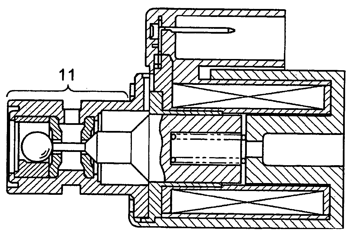
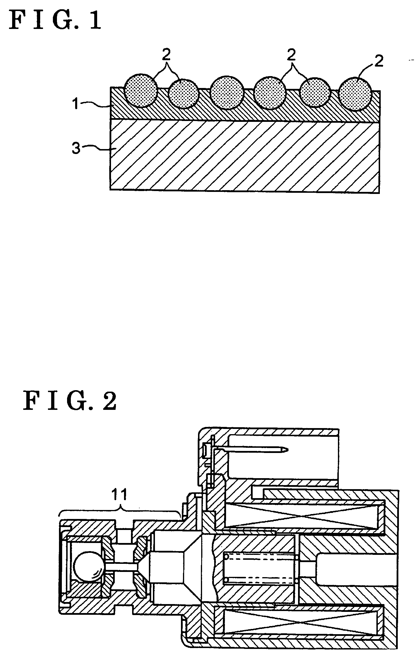
[0017] A fitting member according to the present invention forms, together with a fitted member, a fitting structure between a protruding portion and a hole portion, e.g. a shaft and a bearing. The fitting member comprises a fitting member unit and a lubricating layer that covers the fitting member unit. The lubricating layer includes a synthetic resin layer that has more elasticity than material used for the fitting member unit and inorganic particles that protrude from a surface of the synthetic resin layer. The fitting member according to the present invention can enhance its wear resistance and practically enhance a dimensional tolerance of the fitting member relative to the fitted member. Thus, irrespective of the type of the material of the fitting member unit, and irrespective of the type of the structure that forms the fitting structure, the fitting member according to the present invention can be used for various types of the fitting structure between the shaft and the bear...


PUM


Abstract

A fitting member that forms, together with a fitted member, a fitting structure between a protruding portion and a hole portion, the fitting member comprises a fitting member unit and a lubricating layer that covers the fitting member unit, wherein the lubricating layer includes a synthetic resin layer that has more elasticity than material used for the fitting member unit and inorganic particles that protrude from a surface of the synthetic resin layer.

Description

[0001] This application is based on and claims priority under 35 U.S.C. § 119 to Japanese Patent Application 2004-089943, filed on Mar. 25, 2004, the entire content of which is incorporated herein by reference. FIELD OF THE INVENTION [0002] This invention generally relates to a fitting member for forming, together with a fitted member, a fitting structure between a protruding portion and a hole portion, and a manufacturing method for the fitting member. BACKGROUND [0003] A fitting member forms, together with a fitted member, a fitting structure between a shaft and a bearing. The fitting member is formed so as to correspond to a structure or a dimension of the fitted member. When the fitting member forms, together with the fitted member, the fitting structure between a shaft and a bearing by means of a running fit, a interference fit or the like, the fitting structure requires a high level of dimensional accuracy. Thus, a cold forging needs to be preformed on several occasions and an...

Claims


Application Information

Patent Timeline
Patent Type & Authority Applications(United States)
IPC IPC(8): F16K31/06F16B4/00F16C33/10F16C33/14F16H61/00H01R13/627
CPCF16K31/0637F16H61/0003
Inventor KOBAYASHI, HIROSHI
Owner AISIN SEIKI KK
Why Eureka
Try Eureka