Eureka AIR delivers breakthrough ideas for toughest innovation challenges, trusted by R&D personnel around the world.

Amplifiers and amplifying methods for use in telecommunications devices

Inactive Publication Date: 2005-09-29
AVAGO TECH WIRELESS IP SINGAPORE PTE
View PDF24 Cites 0 Cited by
  • Summary
  • Abstract
  • Description
  • Claims
  • Application Information

AI Technical Summary

Benefits of technology

[0009] According to certain embodiments of the present invention, a signal strength indicator circuit is provided. This circuit includes a first amplifier stage for receiving a first input signal from a first mixer and a second input signal from a second mixer. This circuit also includes a second amplifier stage for receiving a first set of differential inputs from the first amplifier stage. In addition, this circuit includes a third amplifier stage for receiving a second set of differential inputs from the second amplifier stage. Further, this circuit includes an output port for emitting an output signal that is a rectified combination of the first input signal and the second input signal.
[0010] According to certain other embodiments of the present invention, a method of processing signals input into a signal strength indicator circuit is provided. The method includes a first receiving step, wherein a first input signal is received from a first mixer and a second input signal is received from a second mixer in a first amplifier. The method also includes a forwarding step, wherein a

Problems solved by technology

One substantial disadvantage of providing separate paths for each signal that is input into a signal strength indicator circuit is that the separate components in each path make the circuit larger.
Another substantial disadvantage of providing separate paths is that, since twice as many electronic components are needed to form two paths than one, the circuit with two paths requires a relatively large amount of power to operate.
In addition, this additional power consumption often requires more complex cooling.
Hence, at least in view of the above, currently-available signal strength indicator circuits are less than ideal for inclusion in telecommunications devices.

Method used


Image

  • Amplifiers and amplifying methods for use in telecommunications devices
  • Amplifiers and amplifying methods for use in telecommunications devices
  • Amplifiers and amplifying methods for use in telecommunications devices

Examples


Embodiment Construction

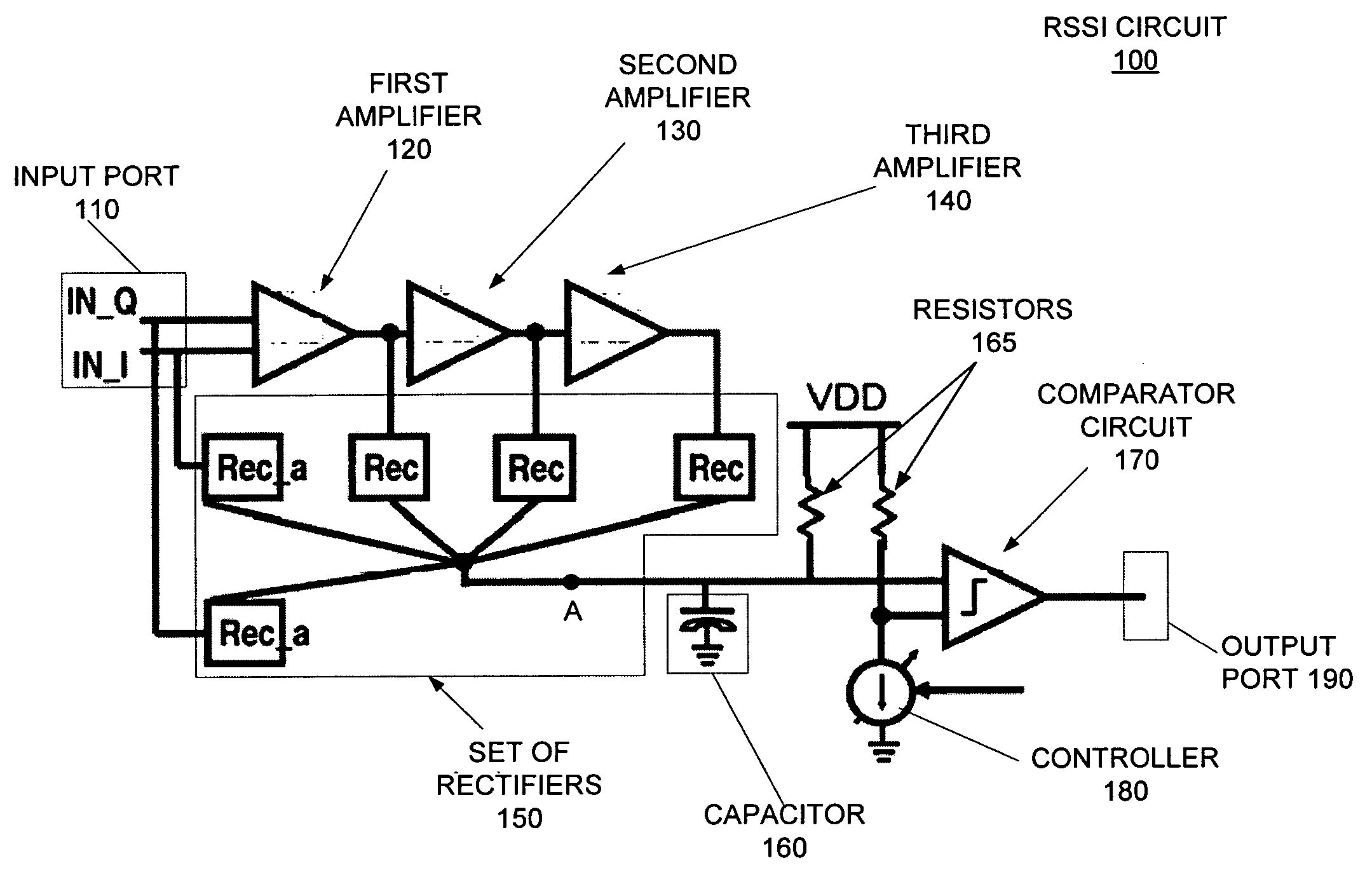
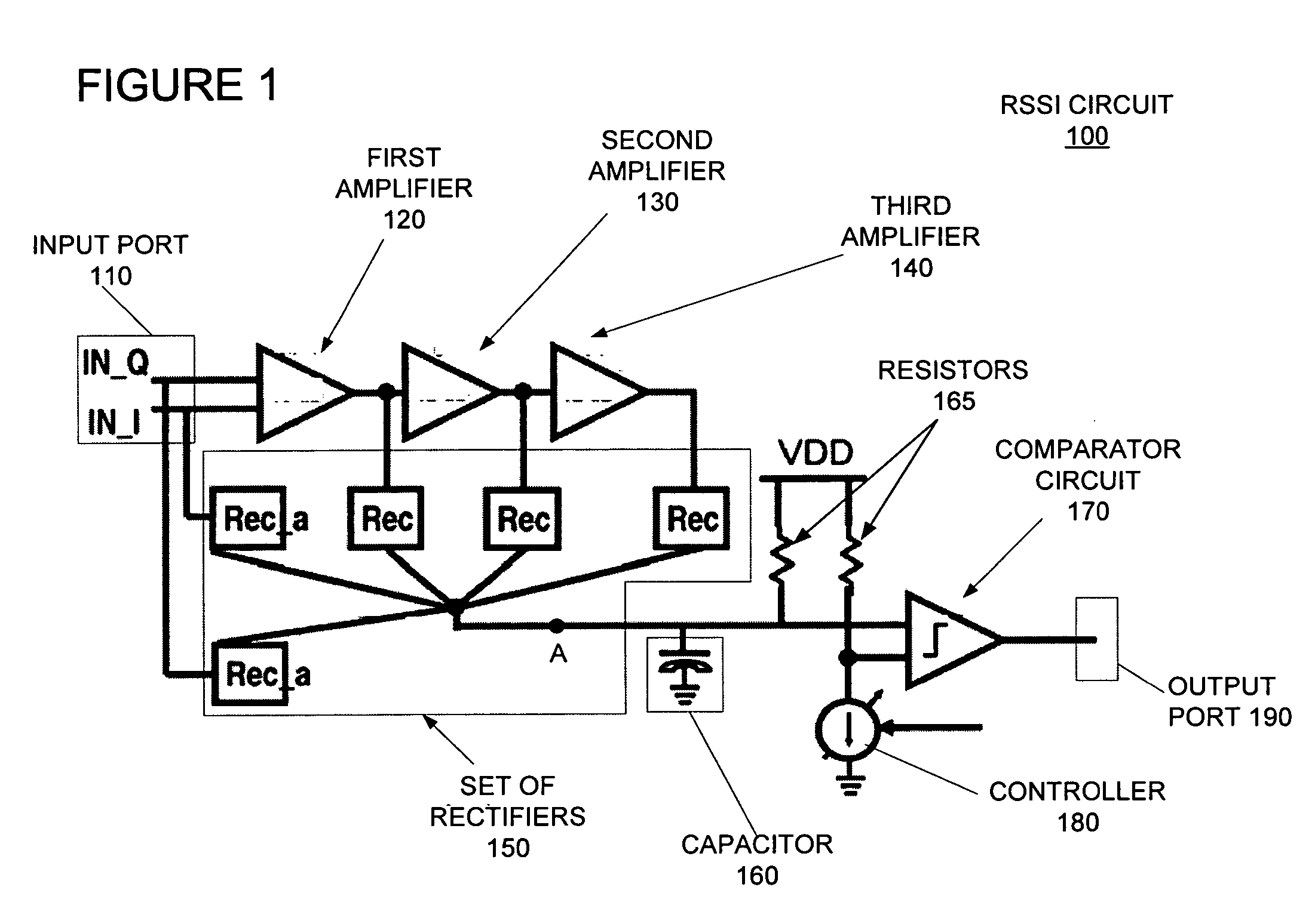
[0017]FIG. 1 illustrates a schematic representation of a Received Signal Strength Indicator (RSSI) circuit 100 that may be included in telecommunications devices according to certain embodiments of the present invention. In operation, circuit 100 receives signals through input port 110. The signals received at input port 110 are typically AC components of RF signals received by a telecommunication device that includes circuit 100.

[0018] Usually, before reaching input port 110, an AC component has been amplified by an amplifier outside of circuit 100 such as, for example, a Low-Noise Amplifier (LNA) that is operably connected to input port 110. After amplification, the AC component is typically mixed down to an Intermediate Frequency (IF) by a mixer operably connected between the outside amplifier and input port 110.

[0019] As illustrated in FIG. 1, circuit 100 may receive both a Q input signal (IN_Q) and an I input signal (IN_I) from an IQ mixer that may be operably connected to in...


PUM


Abstract

A signal strength indicator circuit that includes a first amplifier configured to receive a first input signal from a first mixer and a second input signal from a second mixer;. The circuit also includes a second amplifier configured to receive a first set of differential inputs from the first amplifier. The circuit further includes a third amplifier configured to receive a second set of differential inputs from the second amplifier stage. Even further, the circuit includes an output port for emitting an output signal that is a rectified combination of the first input signal and the second input signal. Also, a method of processing signals input into a signal strength indicator circuit.

Description

BACKGROUND OF THE INVENTION [0001] 1. Field of the Invention [0002] Certain embodiments of the present invention are directed generally to amplifiers that may be included in electronic circuits that are commonly used in telecommunications devices. Certain other embodiments of the present invention are directed generally at methods of operating telecommunications devices with such amplifiers. [0003] 2. Description of the Related Art [0004] Amplifiers are electronic components that are commonly included in a variety of electronic circuits, some of which are included in currently-available telecommunications devices. For example, amplifiers are often included in Received Signal Strength Indicator (RSSI) and / or Transmitted Signal Strength Indicator (TSSI) circuits, where amplification of signals received by a telecommunications device is desired and / or required for proper operation of the device. [0005] In currently-available telecommunications devices, once a Radio Frequency (RF) signa...

Claims


Application Information

Patent Timeline
IPC IPC(8): H03C1/62H03F1/02H04B7/005H04B17/00
CPCH03F2203/45654H04B17/318H04W52/52
Inventor CHIU, JANICE
Owner AVAGO TECH WIRELESS IP SINGAPORE PTE
Why Eureka
Eureka Blog
Learn More