Screw head punch

a screw head and screw head technology, applied in the direction of threaded fasteners, forging/pressing/hammering apparatus, forging/hammering/hammering machines, etc., can solve the problems of socket deformation, punch force bounce, and damage to the punch head, so as to prolong the service life of the punch and improve the structure of the punch

Inactive Publication Date: 2005-09-29
HOME REEN ENTERPRISE
View PDF6 Cites 3 Cited by
  • Summary
  • Abstract
  • Description
  • Claims
  • Application Information

AI Technical Summary

Benefits of technology

[0005] The primary purpose of the present invention is to provide an improved structure of a punch for the head of a screw to extend the service life of the punch and upgrade the quality of the screw. To achieve the purpose, wings are provided on the sides of the punch head at a lever lower than that of the punch head so that when the punch is used to punch for a socket on the head of the screw, a flute slightly recessed will be formed on the sides of the socket to serve as a point for releasing the pressure incurred from the punching process, thus to prevent deformed socket or creation of stress concentration point on the corner of the socket.

Problems solved by technology

However, in the punching for comparatively complicated form of socket, e.g., cross, square, polygonal or their combinations, the concentration of stress at certain point occurs resulting in bouncing of punch force back to the punch or direct application of the force on the screw head during the punching process.
Accordingly, the head of the punch is damaged in short time, the socket is deformed or cracks appear on the corner of the socket.
However, the structure of the punch 1 has served its purpose to punch for a square socket on the head of the screw, the over-concentrated stress results in that the damaged punch to cause extra cost of punching; that the square socket is deformed to cause the failure in a sound insertion between the head of the screw and the tool (e.g. a screwdriver) thus to affect the fastening; or that cracks appear on the four corners of the square socket to cause collapse when the square socket is driven by the screwdriver thus to prevent the fastening.

Method used


Image

  • Screw head punch
  • Screw head punch
  • Screw head punch

Examples


Embodiment Construction

[0014] The following descriptions are of exemplary embodiments only, and are not intended to limit the scope, applicability or configuration of the invention in any way. Rather, the following description provides a convenient illustration for implementing exemplary embodiments of the invention. Various changes to the described embodiments may be made in the function and arrangement of the elements described without departing from the scope of the invention as set forth in the appended claims.

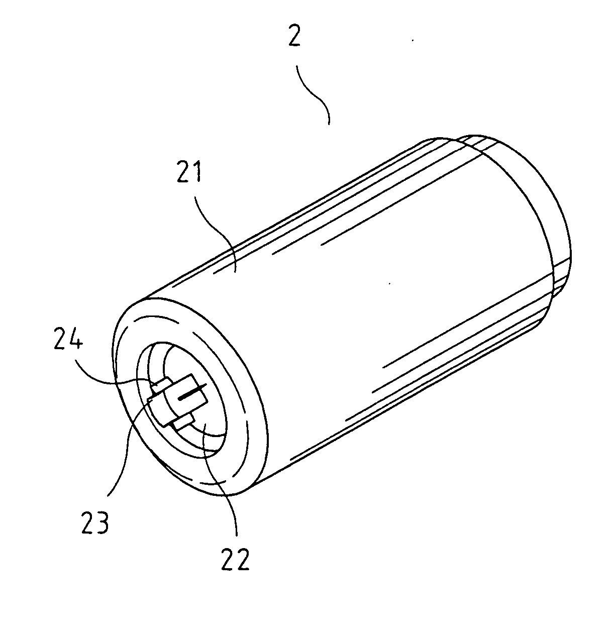
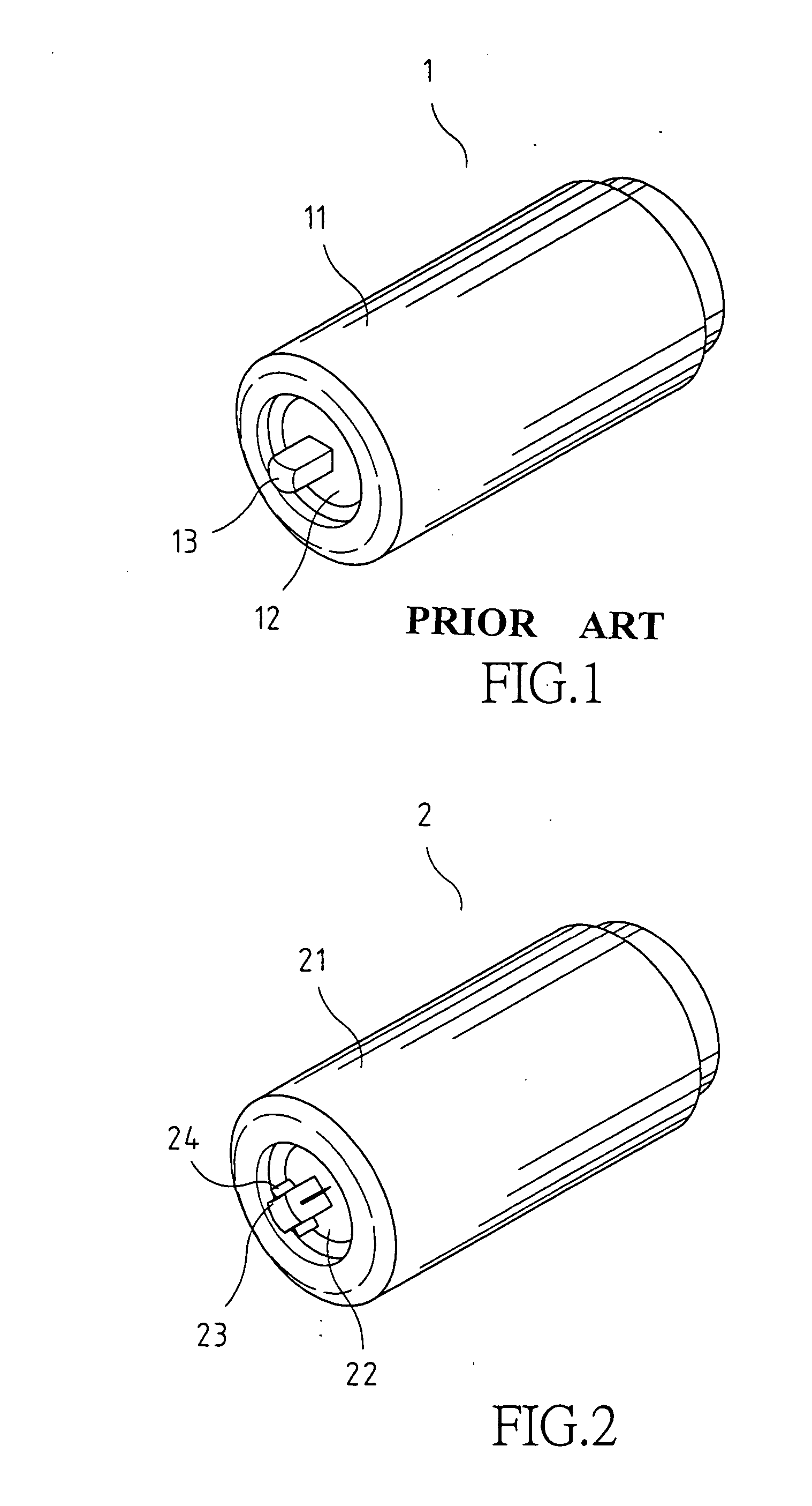
[0015] Referring to FIG. 2, the basic configuration of a punch 2 of the present invention is the same as that of the prior art by having a recess 22 formed on an end 22 of a body 21 of the punch 2; and a punch head 23 protrudes from the center of the recess 22 and is made in square with its end gradually extending toward the center from four corners to form a conic. In the present invention, four wings 24 are each respectively extended from four sides of the punch head 23 at a level lower than ...


PUM

PropertyMeasurementUnit
shapeaaaaaaaaaa
shapesaaaaaaaaaa
punching forceaaaaaaaaaa

Abstract

An improved punch to punch socket on the head of a screw that extends the service life of the punch and upgrades the quality of the screw by having a recess formed on one end of the body of the punch, a punching head protruding from the center of the recess, and multiple wings are respectively extended from the sides of the punching head at a level lower than that of the head of the punch to create traces to release punching pressure to avoid deformed socket or formation of stress concentration point at the corner of the socket.

Description

BACKGROUND OF THE INVENTION [0001] (a) Technical Field of the Invention [0002] The present invention is related to a punch for screw head, and more particularly, to one that extends service life of the punch and upgrades quality of the screw. [0003] (b) Description of the Prior Art [0004] A screw, though a small element among all hardware products, is a must for the assembly of various types of objects. To facilitate driving a screw, the on the surface of the head of the screw is usually provided with a socket either in flat, cross or square shape. To prevent the socket from restricting the use of the tool, e.g., a screwdriver, the socket is made in a shape combining two or more than two of the head shapes. In the formation of the socket, a punch is used to punch into the surface of the screw head when the screw is molded. Each punch is subject to more than two hundred rounds of punching the socket; therefore, a very high punching force is created in the punching process. Generally,...

Claims


Application Information

Patent Timeline
Patent Type & Authority Applications(United States)
IPC IPC(8): B21J13/02B21K1/46B21K1/56
CPCB21K1/463B21J13/02
Inventor LIN, KUO CHOU
Owner HOME REEN ENTERPRISE
Why Eureka
Try Eureka