Golf ball trajectory computing system and method of computing trajectory of golf ball

a golf ball and computing system technology, applied in the field of golf ball trajectory computing system and a method, can solve the problems of inability to accurately use such terms, inability to accurately measure the accuracy of the trajectory, and unclear basis for using such terms

Inactive Publication Date: 2005-09-29
YOKOHAMA RUBBER CO LTD
View PDF17 Cites 31 Cited by
  • Summary
  • Abstract
  • Description
  • Claims
  • Application Information

AI Technical Summary

Benefits of technology

[0008] The present invention has been made to solve problems like those described above based on conventional techniques. An object of the present invention is to provide a golf ball trajectory computing system, and a method of computing a trajectory of a golf ball, in which the trajectory of a struck golf ball from when the golf ball is struck until the golf ball lands can easily be found.

Problems solved by technology

There is a problem, however, with the method of measuring the trajectory of a golf ball disclosed in JP 6-323852 A in that, when measuring the trajectory of the golf ball, measurements must be made with the entire golf ball trajectory in a visible state.
Golf balls are small, and the golf ball carry distance exceeds 100 m. Consequently, there is a problem in that the trajectory measurement precision decreases when the entire trajectory is put into frame by using one CCD camera.
However, the basis for using such terms is unclear.
The terms high trajectory, mid trajectory, and low trajectory are unable to accurately describe the characteristics of golf ball trajectories, and thus are not suited thereto.

Method used


Image

  • Golf ball trajectory computing system and method of computing trajectory of golf ball
  • Golf ball trajectory computing system and method of computing trajectory of golf ball
  • Golf ball trajectory computing system and method of computing trajectory of golf ball

Examples


example

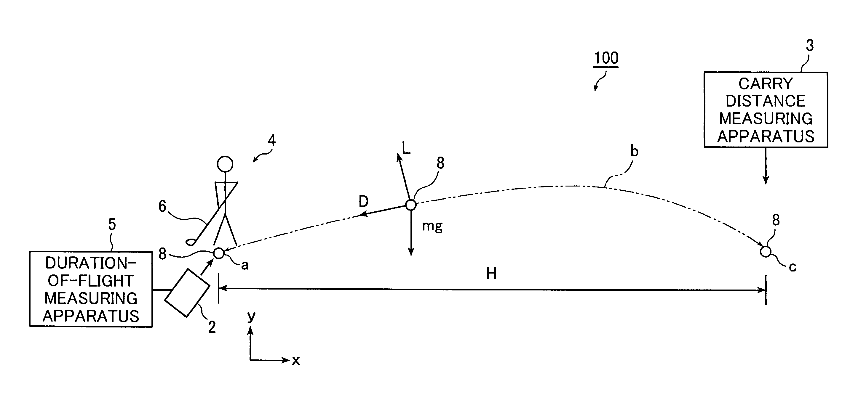
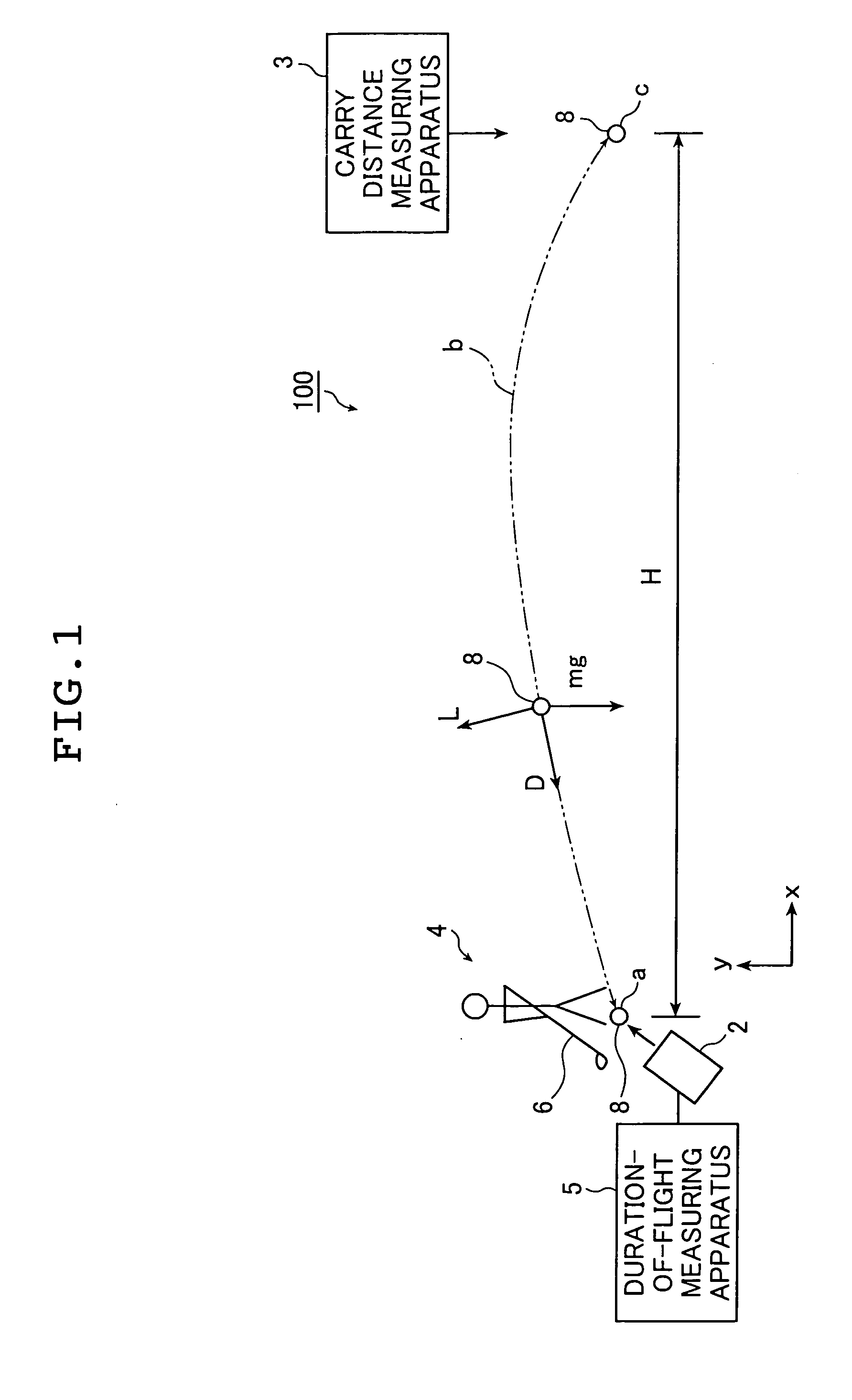
[0103] Specific examples of the present invention is described below by making a comparison.

[0104] In these examples the launch angle is changed using the same golf ball struck by a ball striking machine under conditions of the initial velocity set to 60 m / second and the backspin rate set to 2500 rpm. The carry distance and the duration of flight were then measured at various launch angles. The results are shown in Table 1.

[0105] The average drag coefficient CDa and the average lift coefficient CLa were computed based on Example 1 shown in Table 1 below. The average drag coefficient CDa was 0.216, and the average lift coefficient CLa was 0.177. Based on these computed values, the carry distance HS and the duration of flight TS were computed for Examples 2 to 4 as shown in Table 1.

TABLE 1DurationDuration ofCarryof FlightCarryFlightLaunchDistance(Meas-Distance(Computed)Angle(Measured)ured) (T:(Computed)(Ts:(°)(H: Yards)Seconds)(Hs: Yards)Seconds)Exam-122105.252105.25ple 1Exam-8190...


PUM


Abstract

A trajectory of a struck golf ball from when the golf ball is struck until the golf ball lands is computed by a golf ball trajectory computing system. The system comprises: an initial trajectory measuring portions that measures an initial velocity, a launch angle, and a backspin rate of the golf ball immediately after impact thereof; a carry distance measuring portion that measures a carry distance of the golf ball from an impact point to a landing point where the golf ball lands; a duration-of-flight measuring portion that measures a duration of flight of the golf ball from impact thereof until the golf ball lands; and a computing portions that computes a trajectory of the golf ball based on the measured initial velocity, the measured launch angle, and the measured backspin of the golf ball immediately after impact, and the carry distance and the duration of flight of the golf ball.

Description

INCORPORATION BY REFERENCE [0001] This application claims priority on Japanese patent application No.2004-095488, the entire contents of which are hereby incorporated by reference. BACKGROUND OF THE INVENTION [0002] The present invention relates to a golf ball trajectory computing system and a method of computing the trajectory of a golf ball in order to easily find the trajectory of a golf ball from when the golf ball is struck until the golf ball lands. [0003] Methods of measuring the trajectory of a golf ball in real time, in which trajectory measurement states can be monitored, have been proposed (refer to JP 6-323852 A, for example). [0004] JP 6-323852 A discloses a conventional method of measuring the trajectory of a golf ball. A measuring system thereof is configured by a CCD camera with a shutter, a video memory, a video monitor, and a controller unit. The CCD camera photographs a golf ball. Resultant images undergo high speed comparison processing at a pixel by pixel level,...

Claims


Application Information

Patent Timeline
Patent Type & Authority Applications(United States)
IPC IPC(8): A63B69/36A63B67/02
CPCA63B24/0021A63B69/3658A63B2220/35A63B2024/0037A63B2024/0031
Inventor MIYAMOTO, MASAHIKO
Owner YOKOHAMA RUBBER CO LTD
Why Eureka
Try Eureka