Adjustable tool station

a tool station and adjustable technology, applied in the direction of bearings, linear bearings, metal working apparatus, etc., can solve the problems of inconvenient operation above-disclosed miter saws, and inconvenient use of the user's miter, so as to reduce the overall size of the power tool, reduce the overall size, and reduce the overall siz

Inactive Publication Date: 2005-10-06
THOMSON IND INC
View PDF18 Cites 2 Cited by
  • Summary
  • Abstract
  • Description
  • Claims
  • Application Information

AI Technical Summary

Benefits of technology

[0011] An improved structure of a portable power tool, such as a miter / chop saw, having a reduced overall size and reliable engagement between angularly displaceable parts is attained in accordance with the present invention.
[0012] In accordance with one aspect of the invention, a saw housing receiving a saw blade-is linearly guided along a guide rail, which is not linearly displaceable along with the say housing. As a consequence, the overall size of the power tool is reduced.
[0013] Another aspect of the present invention is directed at minimization of undesirable play between a guide rail and a saw housing during angular displacement of the entire system. To attain this, the guide rail is shaped to mesh with a linear motion bearing segment which is fixed to the saw blade housing. The linear motion bearing segment has a plurality of self-contained roller or ball retainer segments arranged so that the bearing segment and the guide rail engage one another in a substantially play-free manner during pivotal displacement of the miter saw between beveled or angled positions of a saw blade.
[0014] As a consequence, the inventive single guide rail eliminates one shaft or arm of the support system along with a respective plain bushing disclosed by the above-discussed prior art. Furthermore, as a result of the bearing segment and a shape of the guide rail preventing undesired torsional motion of structural components relative to one another, the inventive system is characterized by reduced drag.

Problems solved by technology

A fairly complicated combination of movements can be inconvenient for the user operating the miter saw 10.
Still another disadvantage oa the above-disclosed miter saw may be observed during angular displacement of the saw blade between numerous angular positions which may be accompanied by undesired rotation of the saw head relative to the support arms.
In this position, the upper arm supports some of the load of the saw head and rubs against a plain bushing supporting this arm, which, in turn, causes drag.
In the horizontal arrangement, both arms always support the load of the saw head and; thus, the drag problem manifests itself at an angle smaller than a 45° angle.

Method used


Image

  • Adjustable tool station
  • Adjustable tool station
  • Adjustable tool station

Examples


Embodiment Construction

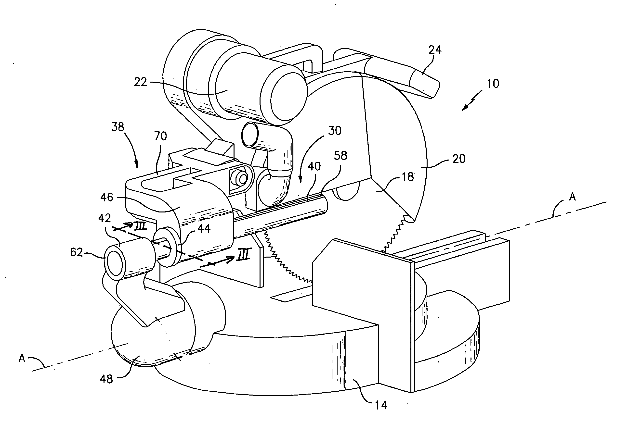
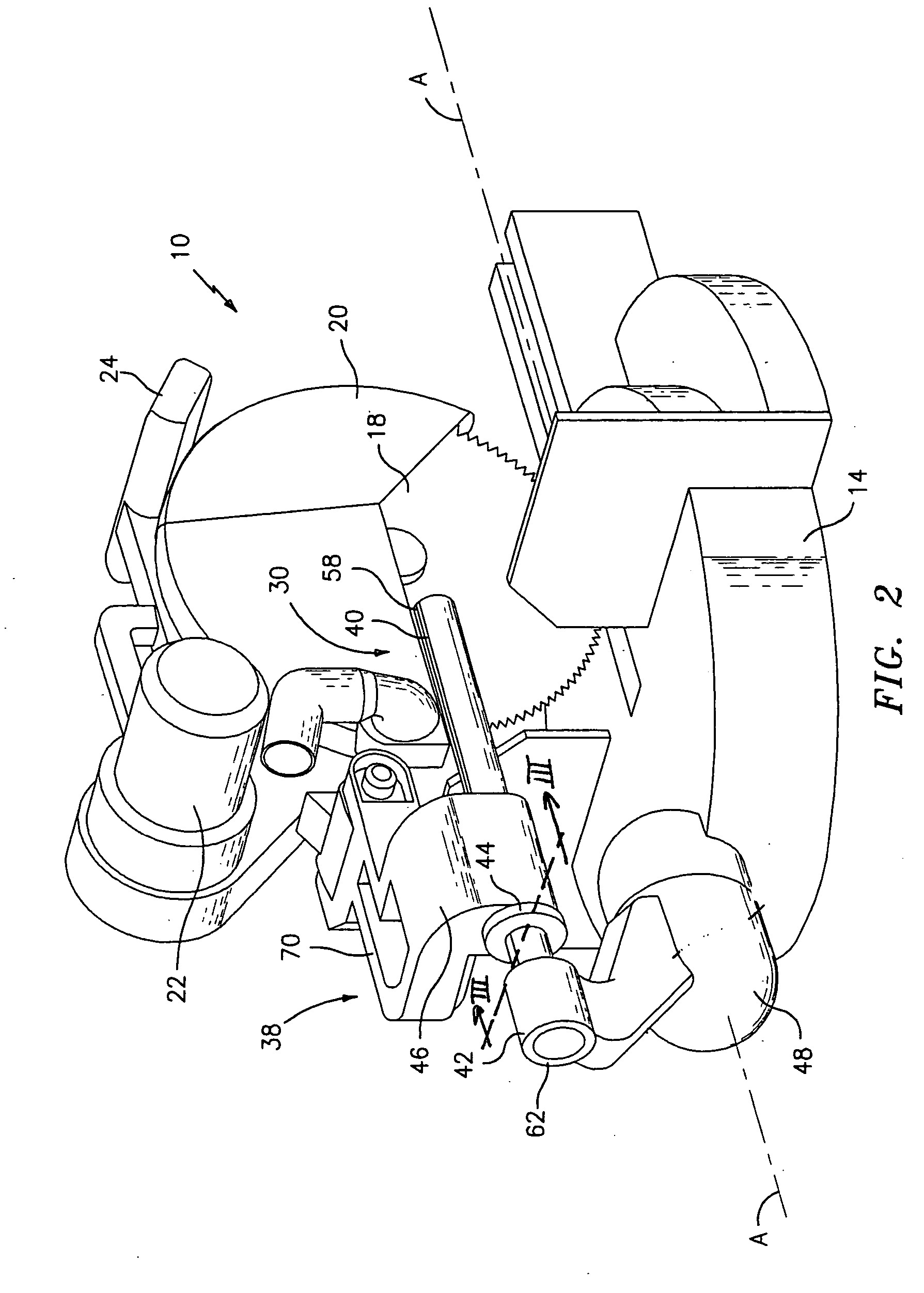
[0025] Referring now to the drawings, in which like reference numerals designate corresponding parts throughout the several views, FIGS. 2 and 5-7 illustrate a compound miter / chop saw 10 incorporating a support and guide assembly 30 in accordance with the present invention.

[0026] The compound miter / chop saw 10 includes a single guide rail 40, which is mounted on the table 14 so that the guide rail 40 does not move linearly along an axis A-A, and a saw housing 38 slidable along the guide rail 40. Linear displacement of the saw housing 38 into a position shown in FIG. 5 along the axis A-A is necessary when a workpiece to be sawed has a substantial size exceeding the diameter of the saw blade 18.

[0027] The compound miter / chop saw 10 further includes a rotatable join 48 mounted rotatably about an axis A-A on the table 14 and a guide rail housing 68 rigidly coupled to the rotatable joint 48 by means of an arm 66 (FIG. 6) for synchronous pivotal motion around the axis A-A. The guide rai...


PUM

PropertyMeasurementUnit
angleaaaaaaaaaa
external torqueaaaaaaaaaa
displacementaaaaaaaaaa

Abstract

A miter saw includes a tool adjustment unit having a joint pivotable about an axis, a guide rail spaced from and coupled to the joint so as to pivot about the axis, a saw housing mounted on the guide rail and a linear motion bearing assembly, which is positioned between the guide rail and the saw housing. The guide rail and the linear motion bearing are so shaped and dimensioned that the saw housing and the guide rail rotationally engage one another in a substantially play free manner to displace a saw blade between a plurality of angled positions.

Description

CROSS-REFERENCE TO RELATED APPLICATIONS [0001] The present application is a continuation-in-part of International Application No. PCT / US01 / 50897, filed Oct. 24, 2001, which claims the benefit of U.S. Provisional Application 60 / 242,850, filed on Oct. 24, 2000.FIELD OF THE INVENTION [0002] The present invention relates to an adjustable tool station. More particularly, the invention relates to a guide assembly rotatably engaging a tool head in a substantially play-free manner to prevent rotation of the tool head. BACKGROUND OF THE INVENTION [0003] Numerous power hand tools assisting a user in accomplishing a variety of tasks are known. Generally, such tools include a base and a tool head for performing a certain task, for example, cutting and / or sawing a workpiece composed of wood, plastic, metal or other various materials. Typically, a saw assembly includes a blade and various actuators adapted to displace the blade linearly along a longitudinal axis, rotate the blade about the longit...

Claims


Application Information

Patent Timeline
Patent Type & Authority Applications(United States)
IPC IPC(8): F16C29/00F16C29/06
CPCF16C29/069F16C29/001F16C2322/39Y10T83/8878Y10T83/7788Y10T83/8773Y10T83/949Y10T83/7772Y10T83/7705Y10T83/7726Y10T83/7697
Inventor NG, ALISONKIM, ERICDALESSANDRO, FRANK
Owner THOMSON IND INC
Why Eureka
Try Eureka