Elevator installation with compensating-means guide

Inactive Publication Date: 2005-10-06
INVENTIO AG
View PDF8 Cites 3 Cited by
  • Summary
  • Abstract
  • Description
  • Claims
  • Application Information

AI Technical Summary

Benefits of technology

[0005] A purpose of the present invention is to create a device of the type described above which does not possess the stated disadvantages

Problems solved by technology

When built in, it occupies a relatively large amount of space which in certain elevator installations is not ava

Method used


Image

  • Elevator installation with compensating-means guide
  • Elevator installation with compensating-means guide
  • Elevator installation with compensating-means guide

Examples


Embodiment Construction

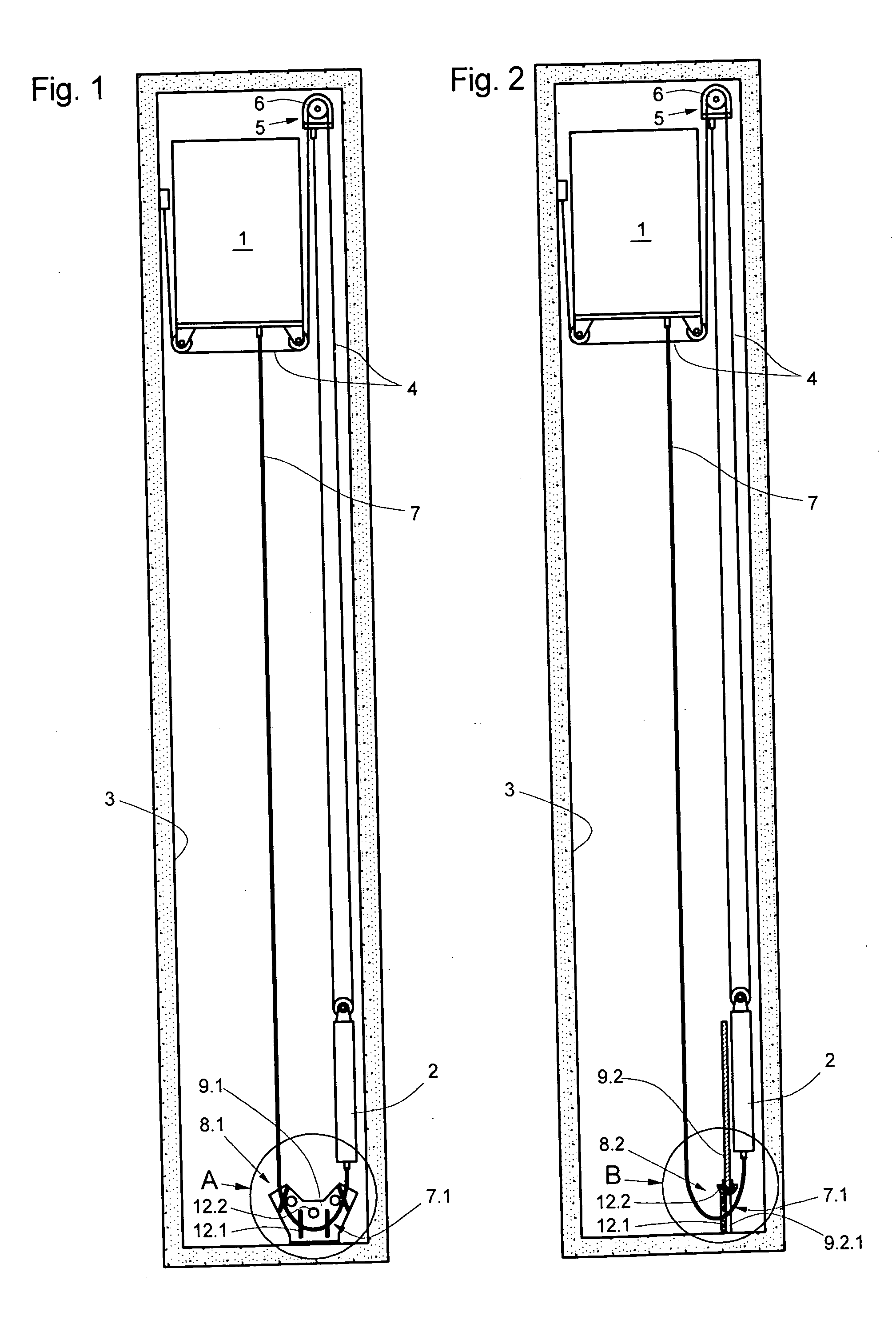
[0029]FIGS. 1 and 2 each show an elevator installation according to the present invention. Shown in both drawings are an elevator car 1 and a counterweight 2 which are installed in an elevator hoistway 3. The elevator car 1 and the counterweight 2 hang on a suspension means 4 via which they are moved vertically by a drive unit 5 having a traction sheave 6 along guide rails which are not shown. Hanging between the elevator car 1 and the counterweight 2 respectively is a compensating means 7 in the form of a loop which is fastened by one of its ends to the elevator car 1 and fastened by an opposite end to the counterweight 2.

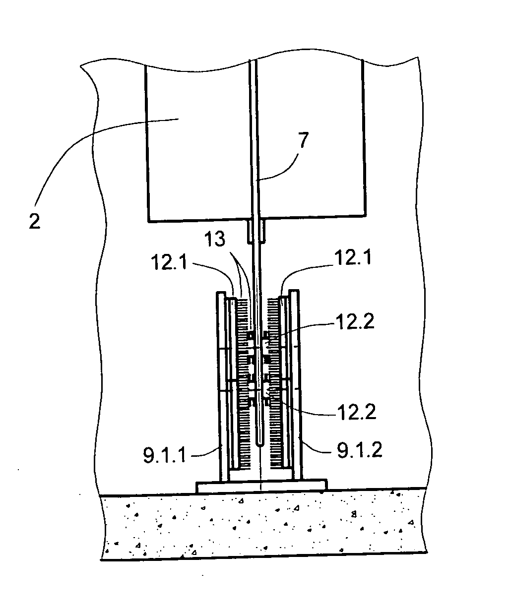
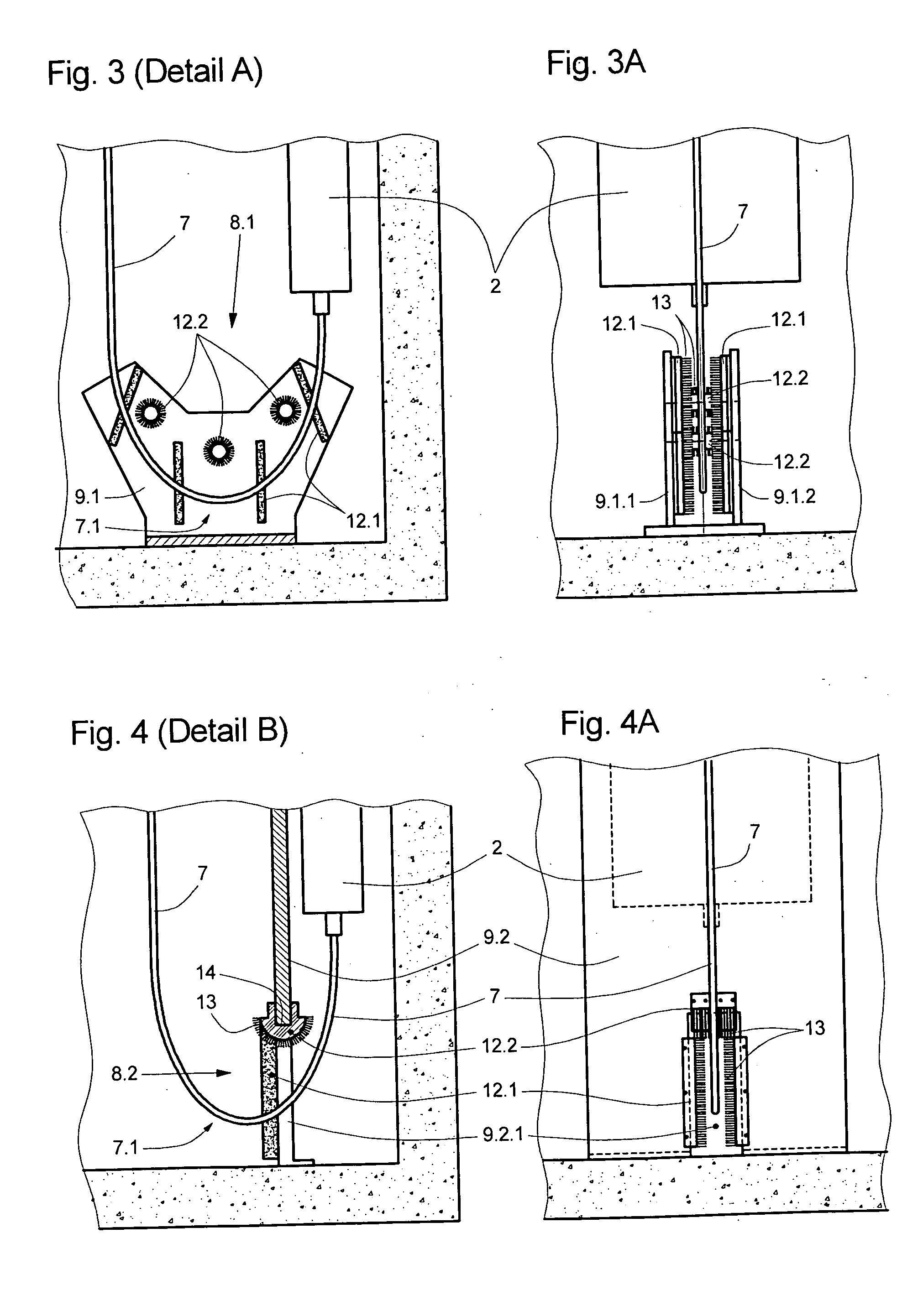
[0030] Visible in FIGS. 1 and 2 are two variants of a compensating-means guide 8.1, 8.2. In each case, these have a number of brushes 12.1, 12.2 which guide the compensating means 7 in the area of its reversal 7.1 perpendicular to the direction of reversal, in the direction of reversal, and also in the vertical direction, i.e. restrict the possible deflection of ...


PUM


Abstract

An elevator installation with an elevator car and a counterweight, a suspension cable suspending the elevator car and the counterweight, and a compensating cable compensating the effect of the weight of the suspension cable, is equipped with a compensating cable guide which for the purpose of guiding the compensating cable has at least one brush.

Description

BACKGROUND OF THE INVENTION [0001] The present invention is an elevator installation with a compensating-means guide. [0002] In association with elevator installations, the term “compensating means” is to be understood as a flexible means in the form of a rope, belt, or chain, which is hung at each of its two ends from the elevator car and the counterweight respectively and forms a hanging loop of compensating means. The purpose of the compensating means is to compensate the effect, on the driving force needed on the traction sheave, of the weight of the suspension and driving means (suspension ropes, suspension belts), which depends on the position of the car in the elevator shaft. [0003] U.S. Pat. No. 6,488,125 shows an elevator installation with a compensating-means guide in which the rope-shaped compensating-means form a loop of compensating-means which in the area of its reversal is guided by a plurality of guide pulleys arranged in a frame. [0004] The compensating-means guide ...

Claims


Application Information

Patent Timeline
IPC IPC(8): B66B7/06B66B7/12
CPCB66B7/068
Inventor MORI, PETERWEINGARTNER, FRANZGENSICKE, KARSTEN
Owner INVENTIO AG
Why Eureka
Try Eureka