Image recording apparatus

a technology of image recording and recording apparatus, which is applied in the direction of printing, other printing apparatus, etc., can solve the problems of color mixing, image quality decline, low productivity, etc., and achieve the effect of preventing color mixing of inks, facilitating color mixing, and easy evaluation of color mixing

Inactive Publication Date: 2005-10-06
FUJIFILM CORP
View PDF7 Cites 21 Cited by
  • Summary
  • Abstract
  • Description
  • Claims
  • Application Information

AI Technical Summary

Benefits of technology

[0014] The present invention has been contrived in view of the foregoing circumstances, and an object thereof is to provide an image recording apparatus capable of preventing color mixing of inks on the surface of the recording medium, while achieving high-speed recording.

Problems solved by technology

However, in cases where a color image is recorded by using a plurality of inks of different colors, then if an ink of one color is recorded in an overlapping fashion onto ink of a different color recorded previously, before that ink has fixed and hardened, then color mixing occurs and image quality declines.
Therefore, productivity is low.
However, no device for fixing or curing the ink that has been deposited on the recording medium is provided, and the ink is simply left to dry naturally.
Therefore, it is not possible always to prevent color mixing in a reliable fashion.
Moreover, Japanese Patent Application Publication No. 04-173250 simply sets a time period greater than the printing delay between adjacent dots, but it does not comprise a device for adjusting fixing or curing, and therefore has the same problems as Japanese Patent Application Publication No. 03-247450.

Method used

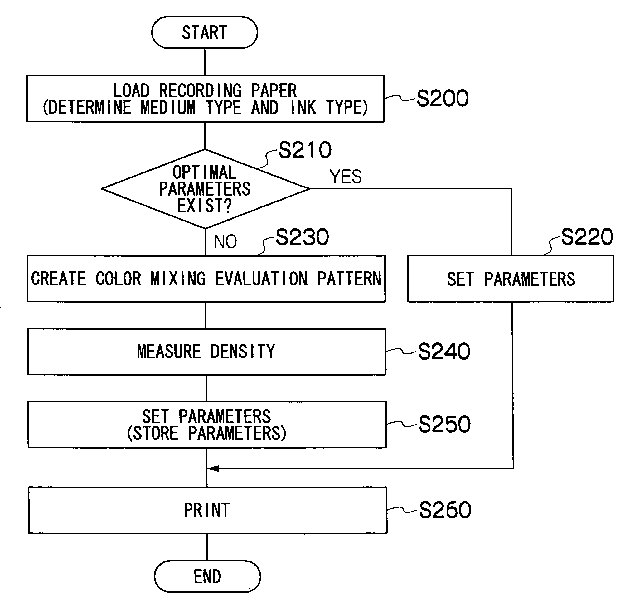
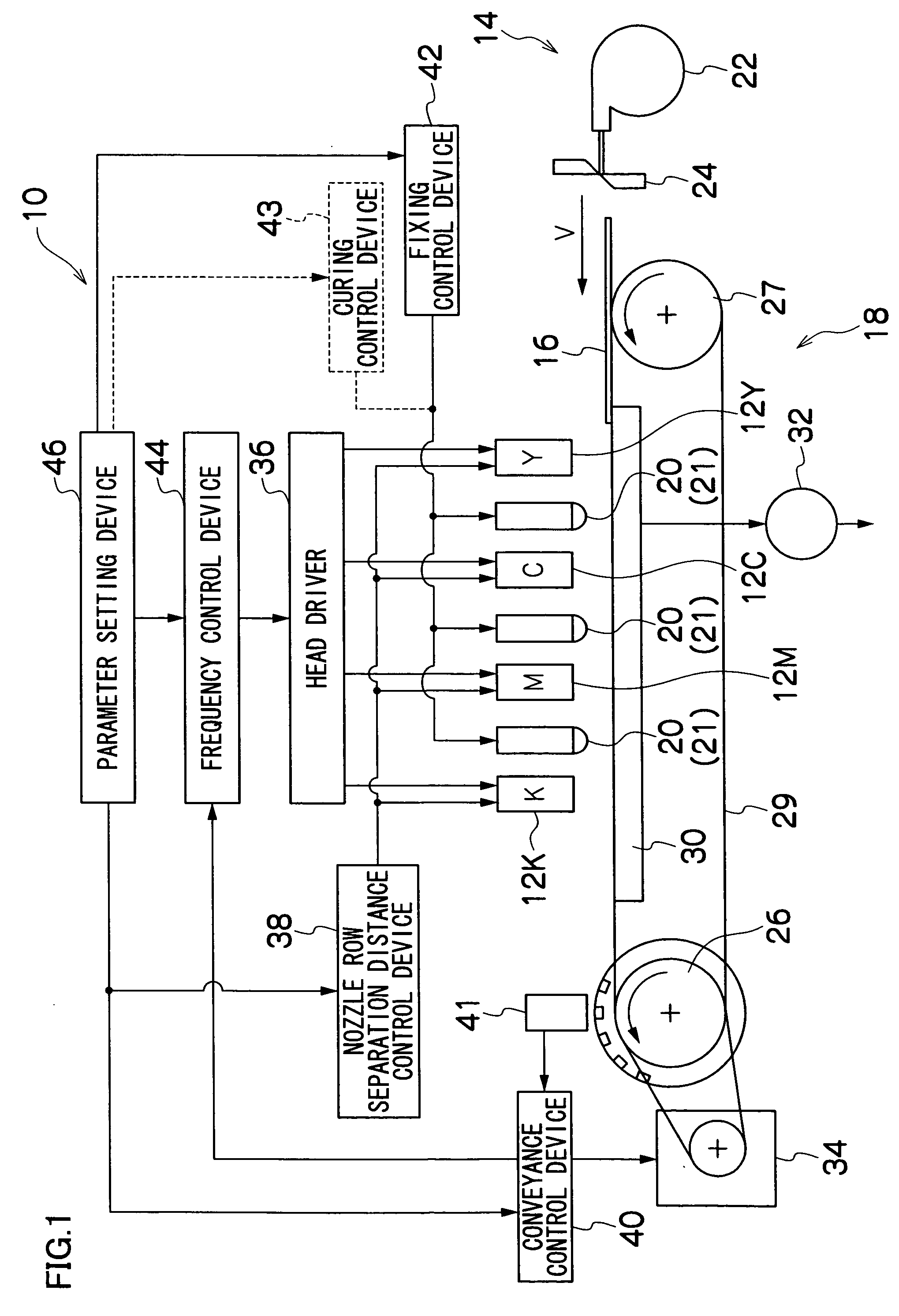
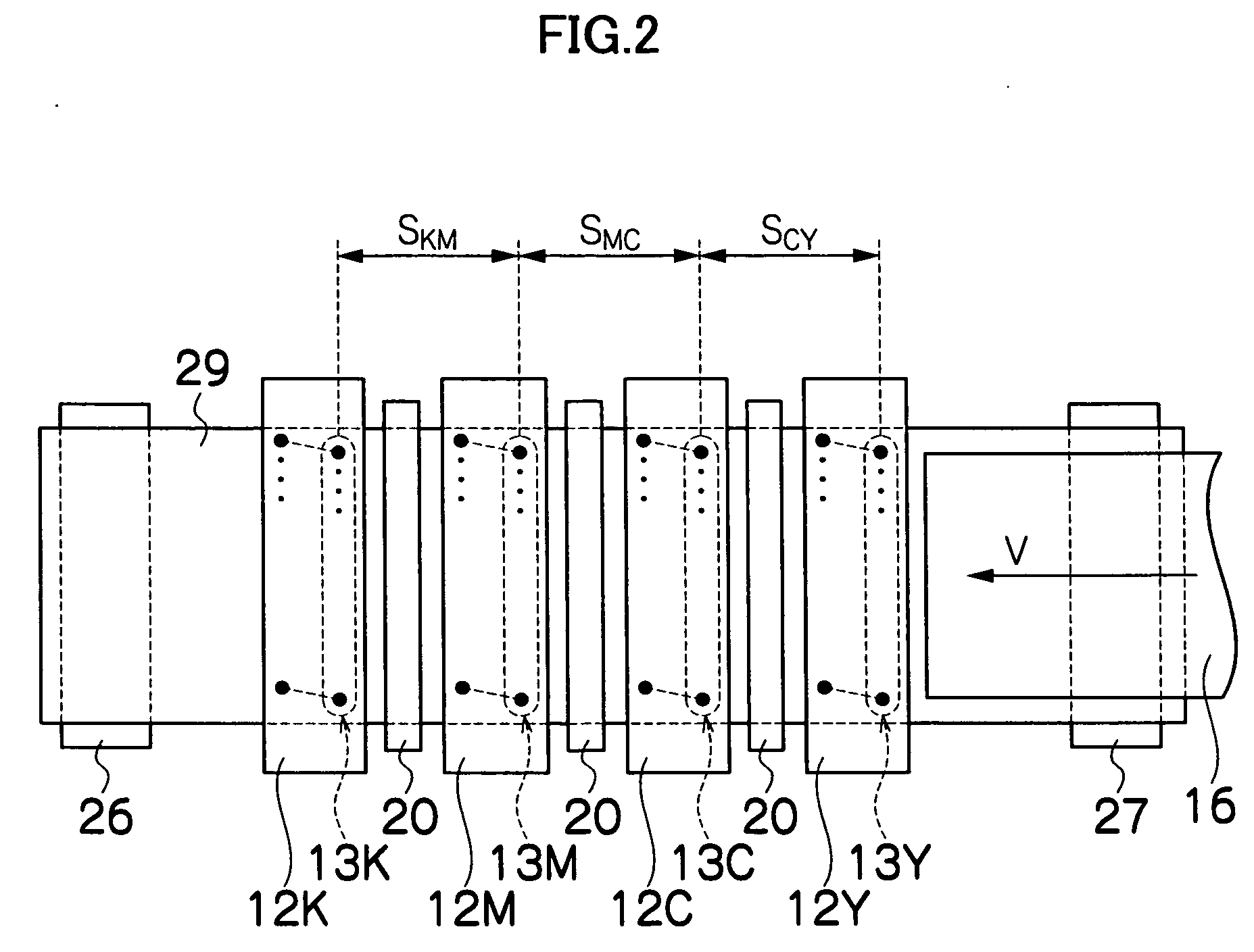

Image

  • Image recording apparatus
  • Image recording apparatus
  • Image recording apparatus

Examples


second embodiment

[0105] Next, the present invention will be described.

[0106]FIG. 8 is a block diagram showing a control device relating to color mixing prevention control, including a plan diagram showing an enlarged view of the region of the print head in an inkjet recording apparatus 110 relating to a second embodiment of the present invention.

[0107] As shown in FIG. 8, the print head 112 according to the second embodiment is a shuttle type head for recording images while moving reciprocally back and forth in the breadthways direction of the recording paper 116. In this case, the print head 112 performs image recording only when moving in one direction from one end toward the other end in the breadthways direction of the recording paper 116, and the print head 112 does not perform image recording when it reaches the far end and moves back to the first end.

[0108] In the print head 112, the nozzle rows 112Y, 112C, 112M and 112K discharging the inks of the respective colors, yellow (Y), cyan (C), m...

first embodiment

[0115] It should be noted that the fixing control device 142, the frequency control device 144, the parameter setting device 146 and the color mixing evaluation print output device 148 all operate in the same fashion as the first embodiment described above, and hence detailed description thereof is omitted here.

[0116] Consequently, the present embodiment differs from the first embodiment in that a shuttle head is used instead of a full line head, and therefore nozzle rows for all four colors are disposed in a single shuttle head, rather than providing nozzle rows for each color in separate line heads as in the first embodiment. However, the fact that the distance between nozzle rows can be changed, and the relationship between the print head (nozzle rows), the recording medium, and the relative conveyance direction, are all the same as in the first embodiment.

[0117] Consequently, in the present embodiment, control for avoiding color mixing can be achieved similarly to the first emb...

third embodiment

[0120] Next, the present invention will be described.

[0121]FIG. 9 is a general schematic drawing including a partial block diagram of the composition of an inkjet recording apparatus relating to a third embodiment of the present invention.

[0122] As shown in FIG. 9, the inkjet recording apparatus 210 is principally constituted by a plurality of print heads 212Y, 212C, 212M and 212K provided respectively for the ink colors yellow (Y), cyan (C), magenta (M) and black (K), a conveyance unit 218 for conveying recording paper 216 forming a recording medium from a paper supply unit 214 to the print heads 212Y etc., and fixing and curing devices 220 for fixing ink that has been discharged onto the recording paper 216.

[0123] As shown in FIG. 9, the recording paper 216 is used by cutting rolled paper (continuous paper) loaded in a magazine 222 into prescribed lengths by means of a cutter 224, but it is also possible to use a plurality of magazines carrying paper of different widths and qual...


PUM


Abstract

The image recording apparatus comprises: a plurality of nozzle rows of respective colors in each of which a plurality of nozzles are arranged independently for each of inks of the respective colors, the plurality of nozzles discharging the inks onto a recording medium; a conveyance device which performs relative conveyance of the recording medium in a relative conveyance direction relatively with respect to the plurality of nozzle rows; and a fixing device which fixes the inks deposited on the recording medium from the plurality of nozzles, wherein the image recording apparatus records an image by discharging the inks of the respective colors onto the recording medium from the plurality of nozzles while the relative conveyance by the conveyance device, and the image recording apparatus further comprises at least one of: a nozzle row separation distance control device which controls a nozzle row separation distance S between a first nozzle row and a second nozzle row which are positioned adjacently in the plurality of nozzle rows of the respective colors and which discharge the inks in a consecutive fashion; a relative conveyance velocity control device which controls a relative conveyance velocity V of the recording medium in the relative conveyance with respect to the plurality of nozzle rows; and a fixing control device which controls a fixing energy of the fixing device in such a manner that a fixing time t1 required for the ink discharged from the first nozzle row to become fixed in the recording medium is a prescribed time period, wherein at least one of the nozzle row separation distance S, the relative conveyance velocity V and the fixing time t1 is controlled so as to satisfy a relationship S / V>t1.

Description

BACKGROUND OF THE INVENTION [0001] 1. Field of the Invention [0002] The present invention relates to an image recording apparatus, and more particularly, to an image recording apparatus for recording images by discharging ink from a plurality of nozzles toward a recording medium, in which color mixing of inks is prevented. [0003] 2. Description of the Related Art [0004] Conventionally, an image recording apparatus (inkjet printer) is known, which comprises an inkjet head (ink discharge head) having an arrangement of a plurality of nozzles and which records images on a recording medium by discharging ink from the nozzles while causing the inkjet head and the recording medium to move relatively to each other. [0005] Various methods are known conventionally as ink discharge methods for an inkjet recording apparatus of this kind. For example, one known method is a piezoelectric method, where the volume of a pressure chamber (ink chamber) is changed by causing a vibration plate forming a...

Claims


Application Information

Patent Timeline
Patent Type & Authority Applications(United States)
IPC IPC(8): B41J2/21B41J2/01B41J11/00B41J11/42
CPCB41J11/002B41J11/425B41J11/007B41J11/00212B41J2/2135B41J2/2146
Inventor KACHI, YASUHIKO
Owner FUJIFILM CORP
Why Eureka
Try Eureka