Liquid container and liquid supplying system

a liquid container and liquid supply technology, applied in water installations, construction, printing, etc., can solve the problems of increased signal lines, inability to meet the requirements of the customer, and disadvantages in manufacturing efficiency and/or cost, so as to achieve discrimination of erroneous mounting of ink containers

Active Publication Date: 2005-10-06
CANON KK
View PDF51 Cites 113 Cited by
  • Summary
  • Abstract
  • Description
  • Claims
  • Application Information

AI Technical Summary

Benefits of technology

[0011] With this structure, the light emission of the light emitting portion is controlled on the basis of a signal inputted through a contact (pad) of an ink container (liquid container) connected with a contact (connector) provided in the main assembly side of the recording device and the information belonging to the ink container, so that even if the ink containers receive the same control signal through the common signal line, only the ink container having the matched individual information can be subjected to the light emission control. In this manner, the light emission control such as lightening of the light emitting portion can be effected for the matched ink container. As an additional feature, the light emission controller can sequentially actuate the light emitti

Problems solved by technology

In the case of the non-PC printing, this is not possible.
If, for example, the ink container is mounted on a wrong position, there is a liability that small ink remaining amount is displayed for another ink container which contains a sufficient amount of the ink.
However, in such a case, it is required to manufacturing ink containers which are different depending on the color and/or kind of the ink, with the result of disadvantages in terms of manufacturing efficiency an

Method used


Image

  • Liquid container and liquid supplying system
  • Liquid container and liquid supplying system
  • Liquid container and liquid supplying system

Examples


Embodiment Construction

[0054] The description will be made as to the embodiments of the present invention in conjunction with the accompanying drawings, in the following order: [0055] 1. Mechanical Structure: [0056] 1.1 Ink Container [0057] 1.2 Modified Example: [0058] 1.3 Ink Container Mounting Portion [0059] 1.4 Recording Device: [0060] 2. Control System: [0061] 2.1 General Arrangement: [0062] 2.2 Connecting Portion: [0063] 2.3 Control Process: [0064] 3. Other Embodiments:

1. Mechanical Structure:

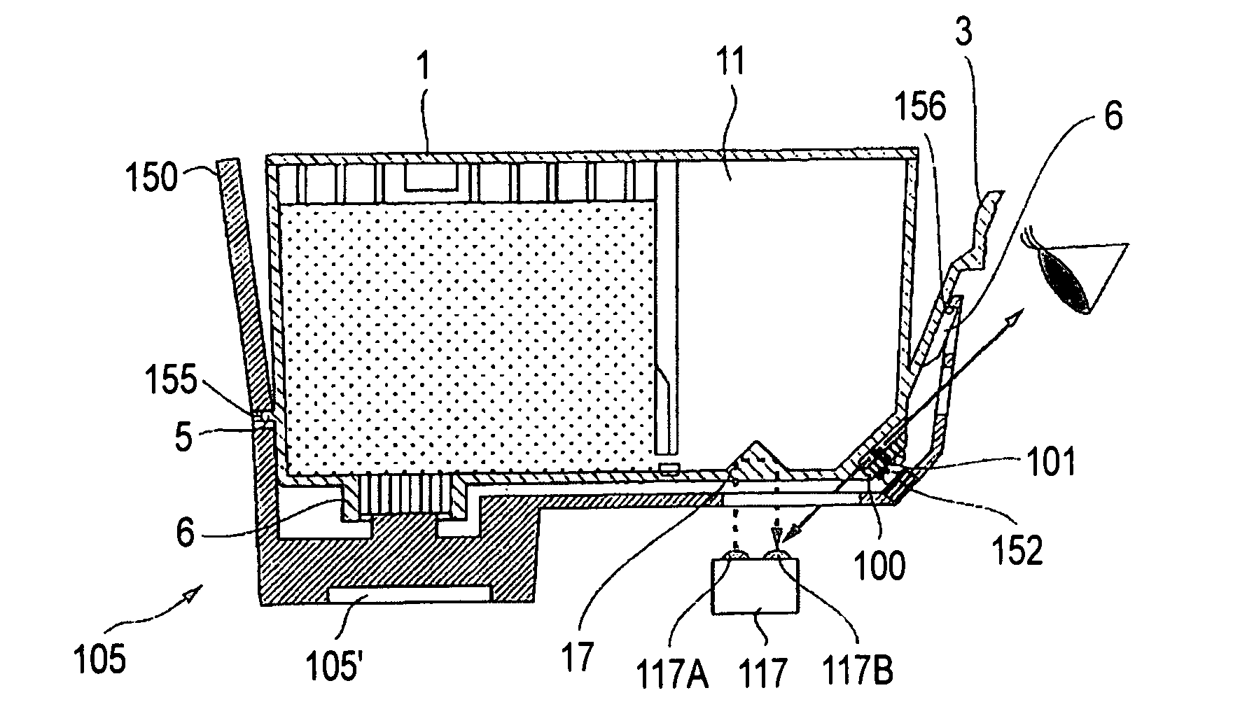
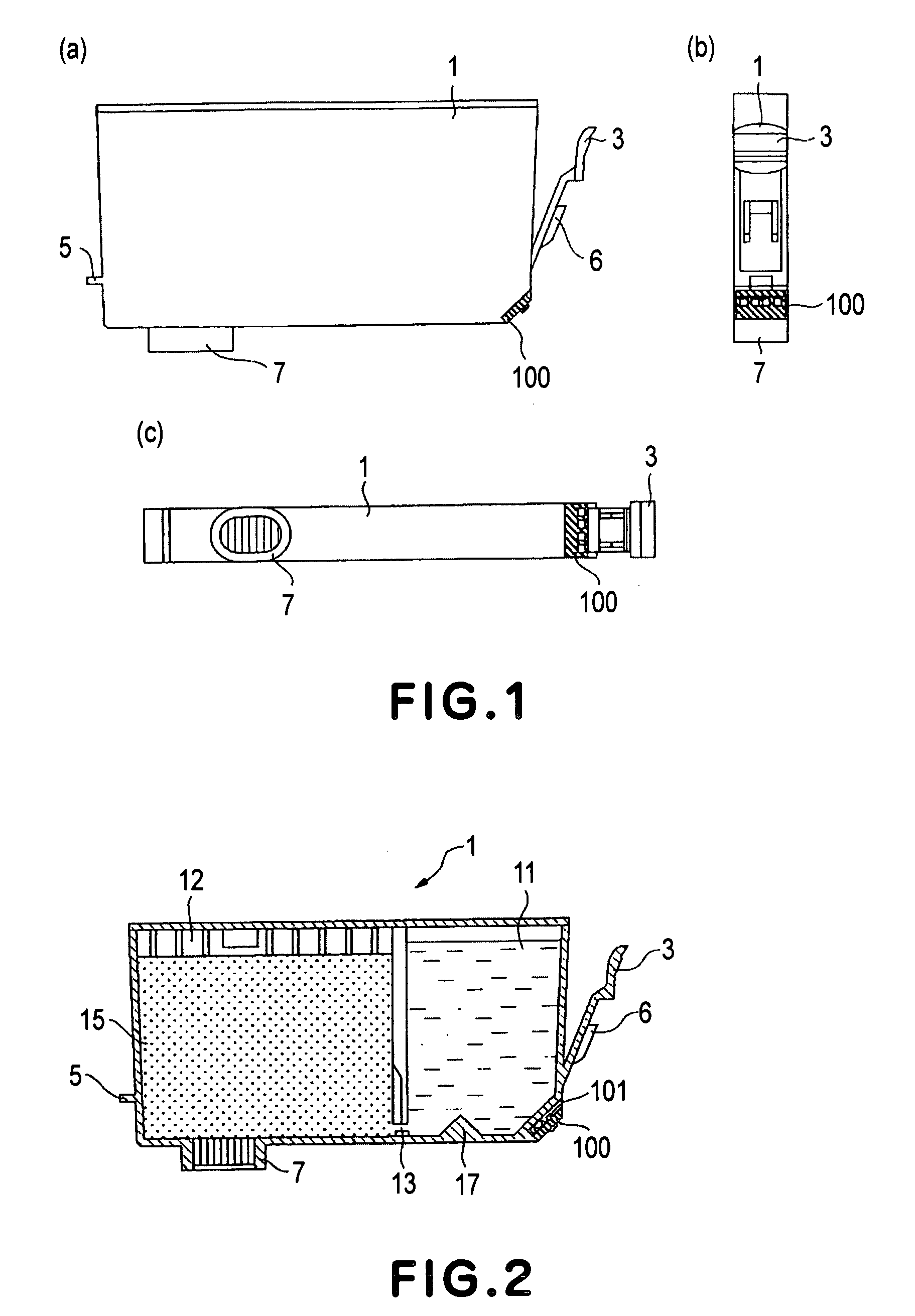
[0065] 1.1 Ink Container (FIG. 1-FIG. 5)

[0066]FIG. 1 is a side view (a), a front view (b) and a bottom view (c) of an ink container according to a first embodiment of the present invention. newpa FIG. 2 is a sectional side elevation of the ink container according to the first embodiment of the present invention. In the following descriptions, the front side of the ink container is the side which is faced to the user who is manipulating the ink container (mounting and demounting operation of the ink container...


PUM


Abstract

A liquid container detachably mountable to a recording apparatus to which a plurality of liquid containers are detachably mountable, wherein the recording apparatus includes apparatus electrical contacts corresponding to the liquid containers, respectively, photoreceptor means for receiving light, and an electric circuit connected with a line which is commonly connected with the apparatus electrical contacts, the liquid container includes a container electrical contact electrically connectable with one of the apparatus contacts; an information storing portion capable of storing at least individual information of the liquid container; a light emitting portion; a controller for controling emission of light of the light emitting portion in response to a correspondence between a signal indicative of individual information supplied through the container electrical contact and the information stored in the information storing means.

Description

FIELD OF THE INVENTION AND RELATED ART [0001] The present invention relates to a liquid container and a liquid supplying system, more particularly, to a liquid container which is capable of notifying a state of the liquid container using light emitting means such as a LED, the state including an ink remaining amount of an ink container for ink jet recording. [0002] With recent wider use of digital camera, the demand is increasing for printing with the digital camera being directly connected with a printer (recording device), that is, non-PC printing. Another increasing demand is for printing by setting a card type information memory medium detachably mountable to a digital camera directly in a printer to transfer the data, and printing them (another non-PC recording). Generally, the ink remaining amount in the ink container of the printer is checked on a display through a personal computer. In the case of the non-PC printing, this is not possible. However, capability of checking the...

Claims


Application Information

Patent Timeline
IPC IPC(8): B41J2/175
CPCB41J2/17546B41J2/17526B41J2/17543E03C1/0402
Inventor MATSUMOTO, HARUYUKIWATANABE, KENJIRO
Owner CANON KK
Why Eureka
Try Eureka