Image processing apparatus

a technology of image processing and apparatus, applied in image data processing, instruments, television systems, etc., to achieve the effect of improving the precision eliminating the discrimination about the convergence of the super resolution process

Active Publication Date: 2013-02-05
CANON KK
View PDF24 Cites 0 Cited by
  • Summary
  • Abstract
  • Description
  • Claims
  • Application Information

AI Technical Summary

Benefits of technology

[0019]It is an object of the invention to provide an image processing apparatus in which an erroneous discrimination about a convergence of a super resolution process can be eliminated and precision of the super resolution process can be improved.

Problems solved by technology

That is, as illustrated in FIG. 9, there is such a problem that an evaluating function for discriminating a convergence, for example, the norm of a convolution of the image before / after the process or the reconstruction image and the point spread function (hPSF) showing the blur and the blur image has a plurality of minimum values and which one of the minimum values is a correct answer is not known.
However, the above system is a method based only on the presumption and there is a possibility of a mixture of an error in a portion where the ringing noises and the real image exist mixedly.

Method used


Image

  • Image processing apparatus
  • Image processing apparatus
  • Image processing apparatus

Examples


first embodiment

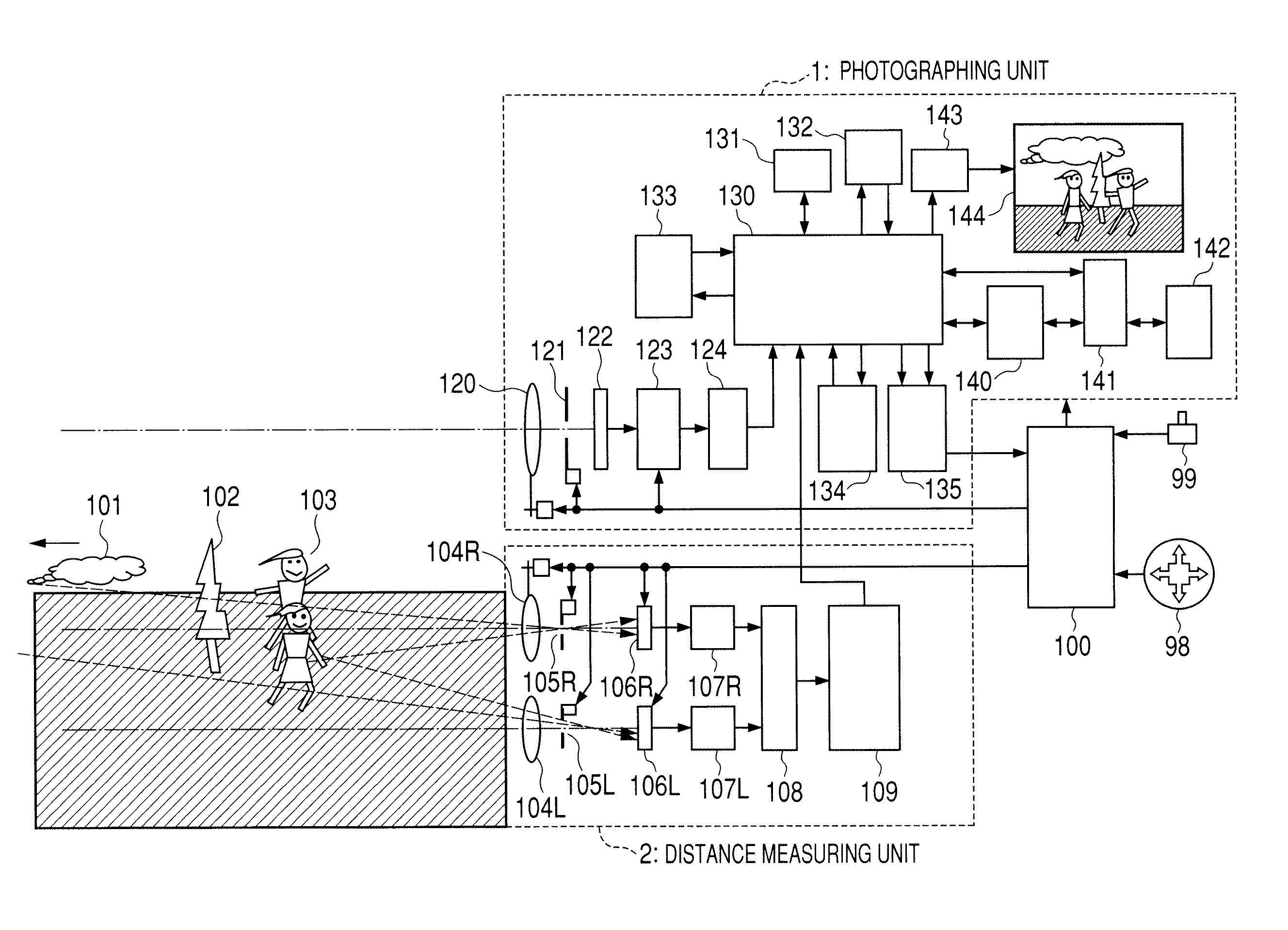
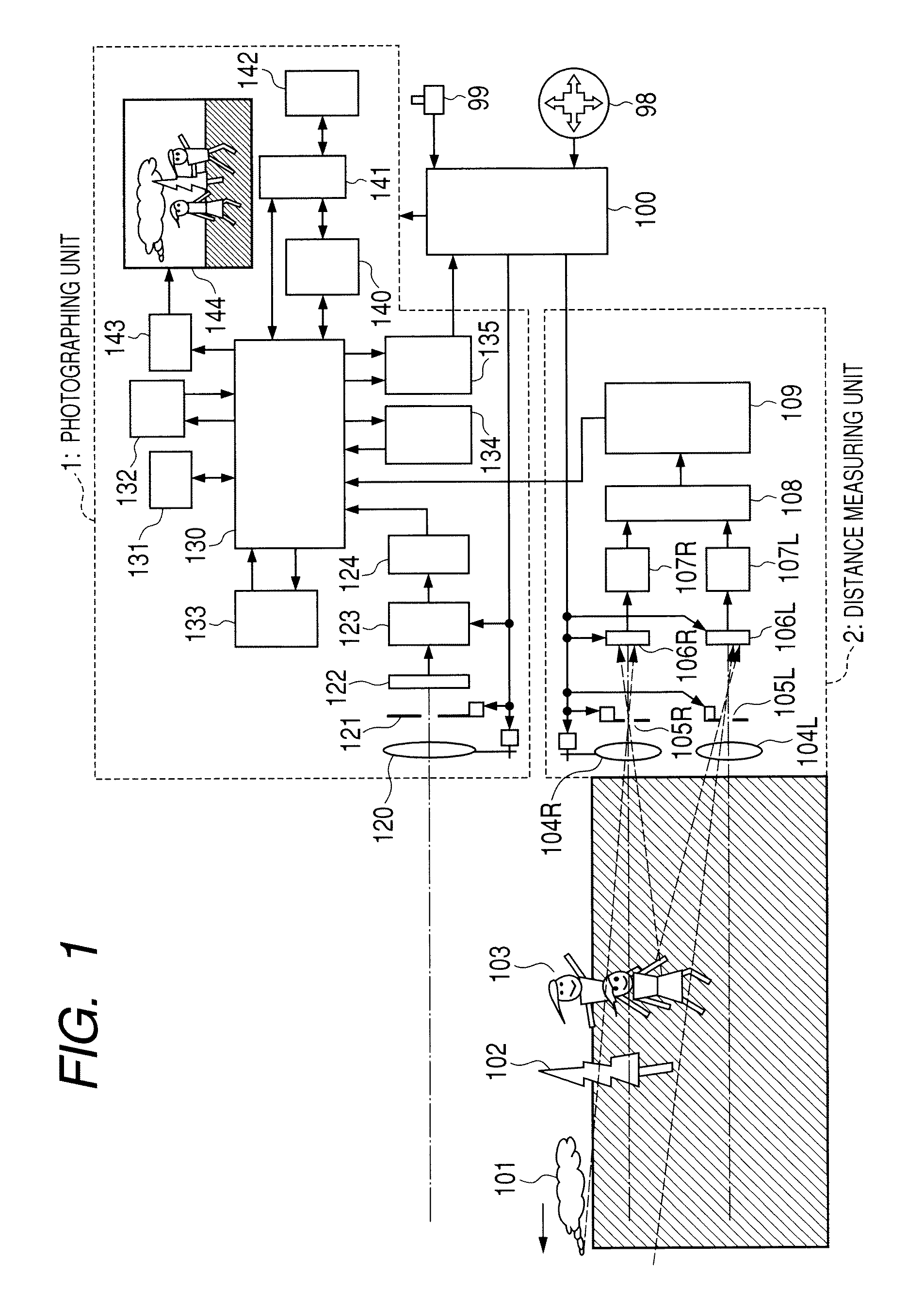
[0032]FIG. 1 is a block diagram illustrating a construction of the first embodiment of an image processing apparatus according to the invention. Particularly, the first embodiment shows an example in which a resolution reconstructing process of an object which belongs to a specific distance layer is executed.

[0033]In the diagram, reference numeral 1 denotes a photographing unit and 2 indicates a distance measuring unit. An example in which a twin-lens stereo method is used in the distance measuring unit 2 is illustrated. An image pickup lens 120, an aperture 121, and an image pickup device 122 such as a CCD are arranged in the photographing unit 1. Reference numeral 123 denotes an ADC (A / D converter) for A / D converting an image pickup signal from the image pickup device 122; 124, a camera processing unit for executing a filtering process or the like; 130, a memory controller; and 131, a memory such as an SDRAM or the like.

[0034]Reference numeral 132 denotes an image reducing unit; 1...

second embodiment

[0064]Subsequently, the second embodiment of the invention will be described by using FIGS. 1, 3, and 6. FIG. 6 is a flowchart illustrating the image reconstructing process in the embodiment. The embodiment relates to an example in which the resolution reconstructing processes of the objects belonging to all of the distance layers, in this case, the three distance layers of the near view (N), the middle distance (M), and the far view (F) are executed. The image reconstructing process in each of the distance layers is fundamentally similar to that in the first embodiment. A construction of the embodiment is similar to that in FIG. 1. Since 1. the operation at the time of preparing for photographing, 2. the operation at the time of photographing, and 3. the operation to confirm the image after photographing are similar to those in the first embodiment, their description is omitted here.

[0065]4. Image Reconstruction.

[0066]4.1 Image Reconstruction Pre-Process.

[0067]When the operator ope...

third embodiment

[0088]Subsequently, the third embodiment of the invention will be described. In the embodiment, an example in the case of reconstructing a deteriorated image on a PC side is shown. That is, an example in which an image photographed by the camera in FIG. 1 is sent to the PC and the deteriorated image is reconstructed on the PC side is shown. FIG. 8 is a flowchart illustrating processes in the embodiment. Since 1. the operation at the time of preparing for photographing, 2. the operation at the time of photographing, and 3. the operation to confirm the image after photographing are the processes on the camera side, they are similar to those in the first embodiment.

[0089]In FIG. 8, the user inserts the flash memory into the PC and activates a deteriorated image reconstruction processing application on the PC. Thus, the deteriorated image reconstruction processing application reads out the photographed images, distance images, and camera parameters from the flash memory, writes them int...


PUM


Abstract

An image processing apparatus in which an erroneous discrimination about a convergence of a super resolution process can be eliminated and precision of the super resolution process can be improved is provided. The apparatus has: a distance measuring unit that measures a distance to an object; a deteriorated image reconstructing unit that reconstructs an image of the object by repetitive calculations; and an end discriminating unit that discriminates an end of an image reconstructing process. In the case of discriminating an end of the image reconstructing process, the end discrimination is made only to a specific distance layer based on information of the distance measured by the distance measuring unit or every distance layer based on the distance information.

Description

CROSS-REFERENCE TO RELATED APPLICATIONS[0001]This application is a continuation of International Application No. PCT / JP2009 / 065878, filed Sep. 4, 2009, which claims the benefit of Japanese Patent Application No. 2008-226976, filed Sep. 4, 2008.BACKGROUND OF THE INVENTION[0002]1. Field of the Invention[0003]The invention relates to an image processing apparatus for reconstructing a deteriorated image.[0004]2. Description of the Related Art[0005]Hitherto, in the case where an object was photographed by an image pickup apparatus such as a digital camera, there is a situation where when the image is seen later, it becomes a deteriorated image due to an out-of-focus or the like. In such a case, a trial to reconstruct the deteriorated image by a super resolution process is made and various kinds of algorithms for the super resolution are considered. For example, Irani and Peleg propose a typical method (hereafter “Irani-Peleg method”) for reconstruction from a plurality of blur images in ...

Claims


Application Information

Patent Timeline
Patent Type & Authority Patents(United States)
IPC IPC(8): G06K9/00
CPCG06T3/4076G06T7/0065H04N5/23212G06T7/55H04N23/815
Inventor WATANABE, IKUO
Owner CANON KK
Why Eureka
Try Eureka